A dial indicator is a critical component used in mechanical, industrial, and management measurements and applications. It is used to instantly measure production and material parameters when the product is in the manufacturing phase and also when it is completed. The dial indicator is used various gauges and measurement equipment due to its ease of manufacturing and simple usage.
In this blog, we will learn about the working principle of dial indicators, parts, constructions, applications, advantages, and disadvantages, and troubleshooting methods.
What is a Dial Indicator & Why Do We Use?
Dial gauges are instruments used to determine the flatness and inclination of things. It is used to assess the roundness of round bars and the inclination of flat workpieces.
- It compares the flatness of an object to the flatness of a standard object.
- Dial indicators are used in the mechanical and industrial sectors to verify the flatness and alignment of various parts and workpieces.
- They are comparatively easy to use than various other gauges like vernier calipers, micrometer gauges, industrial comparators, etc. Where other gauges need the expertise to operate, dial indicators are much easier in terms of use and operations.
Basic Working Principle of Dial Indicator
Dial indicator’s working is based on the use of rack and pinion mechanism, the idea behind its working is the multiplication of a very small upward movement of the spindle at the contact point using the arrangements of gears & levers.
- When pressure is applied, the spindle moves upward, and the dial finger indicates the reading on the dial face.
- Dial indicators consist of a body with a circular graded dial and a contact point coupled by a spiral or gear train such that the hand on the dial face indicates the amount of movement of the contact point.
- They are intended for use with a variety of conventional measuring instruments, including dial indicator snap gauges, hand gauges, portal dials, dial depth gauges, diameter gauges, dial box gauges, etc.
Different Parts of a Dial Indicator Gauge
Contact point
The contact point of the dial indicator is located at the bottom. This is the part of the dial indicator where the surface of the object being measured meets the dial indicator. A contact point should be made of a durable material to produce a reliable reading. Carbide is utilized in dial indicators nowadays as opposed to diamond which was used earlier. This is comparable to what happens to a micrometer’s anvil.
Plunger
The plunger slides in and out with the contact point when pressure is applied. When no pressure is applied to the contact point, the plunger will fully detach from the stem. When pressure is applied, when in measurement mode, the plunger moves in.
The plunger also secures the contact point by holding it inside the plunger casing. The plunger used in dial indicators is constructed using carbide due to its property of harness.
The action of the plunger causes the rack to transmit the movement to the pinion, and the pinion then sends the movement to the gear. Finally, the operators can have the measurement reading with the aid of the pointer mounted to the gear.
Crystal / Lens
It is the outermost part of the dial indicator, which is usually made up of transparent plastic or a glass lens. It lies right on top of the points and scales, protecting them from outside factors such as your hand, wind, or unwanted impurities. The bezel and the outer frame keep the lens in place. Crystals are extremely pleasant in both bright sunlight and dim light conditions. It is replaceable, and it can be done easily when needed.
Scale
There are two scales in the dial indicator, the outer scale, and the inner scale. The larger scale has the largest differences in reading when compared to the inner scale. The scale is shown by the longer pointer and its position encroaches on the rim of the scale circle.
It is generally subdivided into 100 parts. Each section represents the smallest graduation of the pointer, or resolution, on the dial indicator. When getting a reading from a dial indicator, the outer scale reading must be considered.
Since most dial indicators have a resolution of 0.001′′ and a scale of 100 divisions, a full revolution of the long pointer passing through all 100 divisions counts as 0.1′′. Furthermore, to achieve a reading of 1′′, the longer pointer must spin 10 times the whole measuring range.
Bezel
It is the dial indicator’s outermost circular portion. It might be made of plastic or metal. A rubber bezel encircles a few dial indicators. It is commonly used to establish the zero-reference on the inner face of the dial. It has a rough, moveable surface. Once you’ve established the zero-reference, tighten the bezel using the top screw.
Indicator pointer or needle
Two needles are attached for measurements in a dial indicator gauge; the longer and a shorter needle. To get the reading on an outer scale, a longer pointer is used, they are made of plastic or metal and are light weight to achieve higher sensitivity.
The short pointer represents the readings on the inner scale. It spins around the inner scale’s center and serves to point the number markings on the inner scale and offer a reading of how many rotations the long pointer has completed.
Lug Back
The lug back assists in the stability of the dial indicator with the magnetic base support. Without this component, it is very impossible to obtain valid measurements. If you slide the bezel, it will be strong in all directions thus Lug back to assist you to stay steady in any stance.
Gauge Frame
This is the most essential element of the dial indicator gauge since it houses all of the indicator’s components. To safeguard the equipment within, it is composed of metallic material.
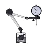

- Measuring range: 0-1"; Resolution: 0.001"
- Flat Back or Lug Back Option Included (hole size 6.5mm); Stem diameter: 3/8" and dial diameter: 2"; Twist and locked bezel, no need a tightening screw and easy to adjust the scale position; Featured anti dust cap
- Pro grade; Smoothy movement; Featured carbide anvil ball
- 2 Magnetic faces available; Max pull 176 lbs (requires 30mm and up thickness metal/steel); The magnet works much better on thicker metal piece, thin metal/steel results less magnetic force
- Manufacturer Certificate Included; 100% satisfy guaranteed
How does the dial indicator gauge work?
A dial indicator works on the concept that a minor pressure applied to a contact point on the spindle is amplified by a complicated system of gears and levers. Let us try to understand how does a dial indicator gauge work!
- The rotation of the gears is represented on the dial indicator scale by a pointer.
- A dial indicator gauge comprises of a body with a circular scaled dial and a contact point connected by a spiral or gear train that spins depending on the pressure applied to the contact point, allowing the hand on the dial face to show the amount of movement of the contact point.
- They are intended to be used with a wide range of traditional measuring instruments due to their ease of use and no complicated setup required. Dial box gauges, portal dials, hand gauges, dial depth gauges, diameter gauges, dial indicator snap gauges, and many more gauges use a similar mechanism.
- The complete instrument is enclosed in a metal casing to secure gears and other parts.
- Response of dial indicator is based on minimum 1mm movement of the spindle. And the scale is divided in to 100 divisions and numbered based on the type and size of the dial indicator.
- Before using a dial indicator, it is calibrated at zero value using slip gauges.
How to Read a dial indicator gauge?
- To understand the working of a dial indicator let us take an example of a dial gauge to measure the flatness of the workpiece.
- When we place the dial gauge on the surface of the workpiece if there’s a variation it will show some value on the gauge.
- Let’s assume the small scale on the indicator show the value of 5 i.e., 3mm and slightly more.
- When the outer scale pointer completes one rotation of the dial then the small scale pointer moves to one division – that is 1mm.
- The outer scale has 100 divisions equal to 1 unit of inner scale. Now let’s take the reading of the outer scale. Let’s assume this scale shows the reading of 53.
- Now we have both the readings, we will now calculate the actual variations in mm using the formula:
- variations (mm) = small scale reading + (outer scale reading x least count)
As per our assumptions
Variations (mm) = 5 + (53 x 0.01)
Thus, Variations = 5.53mm
This is the value of the variation of the surface as calculated by the dial gauge indicator.
What are the different types of dial indicators?
Dial indicators come in various forms based on the type of information shown on the face of the dial, maximum measurement size, types of connection methods, etc. Let’s discuss some of the types here –
Continuous Dial Indicator Gauge
In the continuous dial indicator, the measuring scale is arranged in a continuous pattern, meaning – the scale is printed in a single direction and there is no separation. We can take readings directly based on the deviation of the shorter and long pointer.
Balanced Dial Indicator Gauge
As opposed to continuous dial indicators, that run in a single direction, balanced dial indicators have two sets of values written in opposite directions, with zero in the center. When in use, positive numbers are displayed on the right side of the dial, while negative values are displayed on the left side of the dial indicator.
Reversed Balanced Dial Indicator Gauge
The functioning of the reversed balanced dial indicator is similar to the balanced dial indicator while the difference lies in the arrangement of the scale – positive scale is featured on the left side and negative scale is displayed on the right with zero in the center.
Lever Type Dial Indicator
Dial indicators are composed of a plunger mechanism that slides up and down, causing gears to move and so displaying the reading. The lever type dial indicator is made up of a lever and scroll mechanism that is responsible for the action of gears, which in turn displays the reading through a pointer. These types of dial indicators are compact in design and are easier to use when compared to plunger type indicators.
Test Dial Indicator
Dial test indicators vary from standard dial indicators in a way that they are lever type rather than plunger type and may be used to measure several variables. They are most often used to examine relatively large component surfaces in one or two dimensions, unlike dial indicator that is used for single dimension measurements, such as determining changes in height, flatness, or roundness.
Dial Indicator Based on Connection Method
Dial indicators can also be classified according to the type of connection to the equipment being measured. A C-clamp or a swivel clamp is commonly used to connect the dial indicators; however, a swivel clamp can also be utilized in addition to the swivel post.
What are the prerequisites of a perfect dial indicator gauge?
- There should be proper damping of the dial pointer so that there will be no oscillation of the pointer when the reading is being taken.
- The direction of the movement of the measuring plunger should be indicated by the pointer
- The pressure applied to the measuring head in order to obtain a zero measurement on the dial indicator must be constant across the complete range of measurement.
- The measurement accuracy of the dial gauge should be high for a diverse range of sizes.
- The dial indicator should be able to measure in both the direction without affecting the accuracy of measurement.
Troubleshooting methods of a dial indicator
Problem – The origin position is shifting constantly during the measurement
Temperature fluctuations can affect measurement accuracy; this is due to repeatability error. The solution mentioned here can be used to overcome this problem –
- The workplace temperature should be constant.
- While taking measurements over a long period of time there should be a periodic adjustment of the reference point to the origin. Use master reference to correct the temperature induced drift.
- The stem should be checked regularly and if lose it should be tightened regularly to avoid inaccuracy.
Problem – Improper measurement or the accuracy of measurement is poor
- Check the wear and tear of the components regularly and replace the parts if they are affecting the measurement accuracy.
Where is the Use of dial indicator?
- To examine the irregularities like ovality, roundness, and taper of various surfaces on diverse geometrical shapes.
- It can be also used to determine the differences between the two blocks or distance between two narrow surfaces.
- For precisely measuring deformations such as intension and compression on a machined surface.
- Various positional errors like alignment, squareness, and parallelism can also be examined using the dial indicator.
- Lathe centers can also be aligned using a dial indicator after placing a bar between the centers and placing a dial indicator on it.
- To assure milling machine arbor precision and shaper arm parallelism with the table surface or vice as a reference point.
What are the advantages of a dial indicator?
- When compared to various linear measuring instruments dial indicators are the most perfect instrument for measurement due to their ease of use and fewer skills required.
- In mass production plants, dial indicators can be used for quick measurements by unskilled workers, as they just need to observe the deflection of the pointer.
- In cases where high precision is the requirement dial indicators can be used for dimension control as they can detect extremely low irregularities due to lower least count.
- It can be used for multiple dimensions measurements after attaching it to different types of attachments.
- A combination of different measurements with a specified connection to each other can be easily inspected by the proper design of multiple dial indicator inspection gauges, saving time, and avoiding the need for numerous pieces of equipment.
What are the disadvantages of a dial indicator gauge?
- In the case of products and surfaces of machines having high vibrations use of dial indicators are not possible.
- When the design of a product is complex, and less space is present due to the design intricacies – we need to use dial indicators after tilting it at an angle thus introducing error / precision loss in the dial indicator.
- Due to the shape of the lens or dial crystal, there can be a parallax error.
Refer to Our Videos on YouTube