In this article, we will learn the buckling of columns, along with the definition, meaning, calculations, examples, Euler’s theory, and many more. Let’s explore!
Buckling of Columns – Definition & Meaning
Let’s try to understand the buckling of columns along with basics, definition & meaning.
Buckling Basics
Buckling has undeniably been observed since prehistoric times and mathematically described in some form or another since the late 1700s. As a result, it appears that we may already know everything there is to know about buckling, but the answer is No.
Yes, for a given material and geometry, we have a formalism to define the critical buckling condition. We have a good understanding of how certain boundary conditions define the most probable post-critical state.

However, there are relatively few exceptions to these generalizations.
- This level of current understanding has evolved over two centuries, but it’s only in the last decade that scientists and engineers have begun to push the boundaries and realize the plethora of outstanding problems about buckling.
- Buckling is usually linked to the development of elastic instability, which occurs when an in-plane compression causes an out-of-plane deformation.
- Buckling knowledge has been created in the context of structural failure and prevention for the majority of its quantitative history.
- Buckling, on the other hand, has long been linked to the production of morphological and structural traits in nature.
For this blog only let’s get into a greater aspect of what Buckling actually is!
What is buckling?
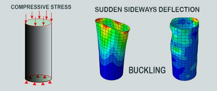
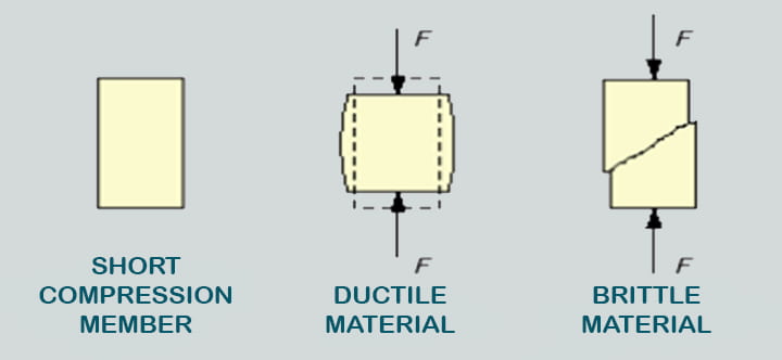
Buckling is a mathematical instability that leads to a failure mode in science. Material failure and structural instability, also known as buckling, are the two major causes of mechanical component failure. For material failures, the yield stress for ductile materials and the ultimate stress for brittle materials must be considered. Buckling occurs when a structural member is exposed to high compressive stresses, likely to result in a sudden sideways deflection.
- The term “deflection” in structural engineering refers to the displacement of a member caused by bending forces. This type of deflection is predictable and can be calculated. Buckling, on the other hand, causes unstable lateral deflection.
- Columns are typically subjected to buckling checks because buckling is caused by compressive or axial forces, which are more frequent in columns than beams.
- Any additional load will cause significant and unpredictable deformations once a member begins to buckle. Buckling frequently resembles crumpling (imagine squashing an empty can of soda).
- The Further load can be sustained in one of two states of equilibrium at a certain stage under increasing load: an undeformed state or a laterally-deformed state.
- The unexpected failure of a structural member under high compressive stress, where the actual compressive stress at the failure point is lower compared to the ultimate compressive stresses that the material can withstand is in practice known as Buckling.
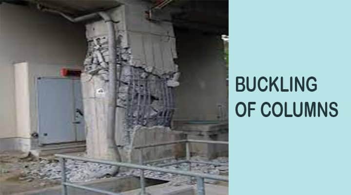
- Reinforced concrete members, for example, may experience lateral deformation of the longitudinal reinforcing bars during earthquakes. Failure due to elastic instability is another name for this mode of failure.
- When a continuous load is applied to a member, such as a column, the load will eventually become powerful enough to cause the member to become unstable.
- The Additional load will result in significant and somewhat unexpected deformations, potentially resulting in a complete loss of load-carrying capacity. It is said that the member buckled and deformed.
- For many types of structures, buckling is a significant failure condition.
Buckling of Columns
Leonhard Euler a famed swiss mathematician developed the Euler theory of column buckling in 1742. Column buckling is a type of deformation caused by axial compression forces. Because of the column’s instability, this causes it to bend.

- This mode of failure is rapid and thus dangerous. A column’s length, strength, and other factors determine how or if it will buckle.
- Long columns will buckle elastically when compared to their thickness, similar to bending a spaghetti noodle. This will happen at a stress level lower than the column’s ultimate stress. The following assumptions underpin Euler’s theory: axial load application point, column components, cross-section, stress limits, and column failure.
- The validity of Euler’s theory is conditional on failure occurring due to buckling.
- This theory disregards the effect of direct stress in the column, crookedness in the column, which exists at all times, and possible changes of the axial load application point away from the centre of the column cross-section. As a result, the critical buckling load may be overestimated by the theory.
Euler’s Theory – Buckling of Columns
According to Euler’s theory, the stress in the column caused by direct loads is small in relation to the stress caused by buckling failure. A formula was developed based on this statement to calculate the critical buckling load of a column. As a result, the equation is based on bending stress and disregards direct stress caused by direct loads on the column.
Euler theory for elastic buckling:
This phenomenon is explained by the Euler equation, also known as Euler’s equation,
P = nπ2 EI/L2
Where,
- L= Length (m)
- P= Allowable load before buckle.
- n= Factor accounting for end conditions
- E= Elasticity Module, Pa (N/m2 )
- I= Moment of Inertia (m4 )
The allowable load decreases as the length increases.
- With shorter columns compared to their thickness, the allowable stress on a column before buckling rises as length reduces, according to the same equation above.
- Another important factor in determining buckling stress is the type of end connections for the column.
- In the Euler equation, each connection, from pinned-pinned to fixed-fixed to fixed-pinned, is represented by a different value of ‘n.’
- Of all the end connections, the fixed-fixed connection has the highest allowable stress before buckling. It takes place differently for different materials in construction.
- This material factor is represented in Euler’s equation by the letters “E” and “I,” which represent different material properties. In steel columns, this occurs elastically. Reinforced concrete, on the other hand, does not fall into this category.
Buckling of Columns Terms
Buckling Strength
The Buckling strength σcr is calculated by dividing the Euler Buckling Load by the cross-sectional area of the column:
- σcr = π2 EI/AL2
Radius of Gyration
If all of a column’s cross-sectional area was massed r away from the neutral axis, The Moment of Inertia of the lumped-area cross-section would be the same as the Moment of Inertia of the real cross-section. The RADIUS OF GYRATION, denoted by r, is given by:
- rx = (Ixx/A)1/2
- ry = (Iyy/A)1/2
Slenderness Ratio
The SLENDERNESS RATIO measures the length of a column in relation to the effective width of its cross-section (resistance to bending or buckling). It is abbreviated as s, is equal to the length of the column divided by the Radius of Gyration. The Euler Buckling Formula is reduced to: by using the Slenderness Ratio and the Radius of Gyration.
- Pcr = π2 EI/L2
- Pcr = π2 E (r/L)2
- Pcr = π2 E/s2
Effective Length
The buckling strength of a column is determined by how it is supported. The EFFECTIVE LENGTH, Le, is used to account for variations in end supports. The Effective Length is the length at which a pinned-pinned column would buckle if it were to buckle. For any column, the Buckling Formula is as follows:
- Pcr = π2 EI/Le2
Buckling Load Factor
Buckling load factor is defined as the indicator of the factor of safety against buckling. It can be also defined as the ratio of buckling load to the currently applied load.
Local Buckling
The possibility of local buckling is arising only when the condition is satisfied which is that the component must have a region where relative thickness to the depth ratio is less than 1/10. In general, it is a rare occurrence but when this condition occurs the result could be sudden and catastrophic.
Euler’s Theory – Assumptions & Limitations
Euler’s Theory – Assumptions
Let’s see the assumptions for Euler’s theory,
- The column is at first perfectly straight.
- The column’s cross-section is consistent along its length.
- The load is axial and moves through the section’s centerline.
- The column’s stresses are within the elastic limit.
- The column’s materials are homogeneous and isotropic.
- The column’s self-weight is ignored.
- The failure of the column is solely due to buckling.
- The column’s length is long in comparison to its cross-sectional dimensions.
- The column’s ends are frictionless.
- The axial compression shortening of the column is negligible.
Euler’s Theory – Limitations
- This theory does not account for the possibility of crookedness in the column, and the load may not be axial.
- The formula derived from the Euler theory of column buckling does not account for axial stress, Furthermore, the critical buckling load may exceed the actual buckling load.
Buckling of Columns Euler’s Theory Examples
Buckling of Columns calculation Examples
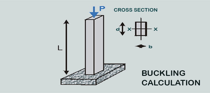
The length of an aluminium (E = 70 GPa) column buried in the earth is L = 2.2 m. and is under axial compressive load P, b = 210 mm and d = 280 mm are the cross-sectional dimensions.

Required:
- The critical load that causes the column to buckle.
- Is the column more likely to bow or yield if the allowed compressive stress in the Aluminum is 240 MPa?
- What is the allowed buckling load if the factor of safety is F.S. =1.95?
Buckling of Columns Solutions
Step#1: Euler Buckler Formula is,
- Pcr = π2 EI/Le2
Where
- Le = Effective Length of the column
In this case, the column is fixed-free in both the x and y directions. A fixed-free column’s effective length is: Le
- Le = 2 L
- Le = 2 x 2.2 [L=2.2m]
- Le = 4.4 m
The x- or y-axis of the column may buckle.
The Moment of Inertia of a rectangle is: I = (base) (height) 3/12
For our values of b and d,
We have:
- Ix = 3.84 x 108mm4
- Iy = 2.16 x 108 mm4
Because of the smaller Euler buckling load, the smaller Moment of Inertia rules. This is the load:
- Pcr = 7711 kN
Step#2: The Critical Buckling Stress is calculated by dividing the Euler Buckling Load by the area, A=bd. As a result, the Buckling Stress is calculated to be:
- σcr = 131.1 MPa
If σcr <240 MPa, the column will buckle (since the buckling tension is attained first as the load is applied);
If σcr >240 MPa, since the yield stress, Sy, is reached first, the column will yield.
Step#3: The Allowable Load on the column, Pallow, for a Factor of Safety of F.S. = 1.95 is exclusively for buckling.
The formula of the Factor of Safety,
F.S. = Failure Load / Allowable Load
- Pallow = Pcr/F.S
- Pallow = 7711 kN/95
- Pallow = 3954 kN
Buckling of Columns More Examples
- Metal building columns that are overburdened.
- Bridge members that are compressive.
- Submarine hull and roof trusses.
- Excessive torsional and/or compressive pressure on metal skin on aircraft fuselages or wings.
- An I-thin beam’s web with significant shear force.
- An I-beam with a narrow flange that has been subjected to extreme compressive bending.
Buckling Analysis
- Buckling Analysis is a finite element analysis technique that can address all buckling problems that cannot be solved by human calculations. The most frequent Buckling Analysis is Linear Buckling Analysis (LBA).
- In contrast to Linear Buckling, the nonlinear technique provides more robust solutions.

- The linear finite element analysis method can be used to predict material failure.
- To put it another way, K δ = F is obtained by solving a linear algebraic problem for the unknown displacements.
- The resulting strains and stresses are compared to the component’s design stress (or strain) allowables across the component.
- It is presumed that material failure has occurred if the finite element solution shows places where these allowables have been exceeded.
- The stiffness of a component, not the strength of its materials, determines the load at which it buckles.
- Buckling is the loss of component stability that is usually unrelated to material strength. This loss of stability usually happens within the material’s elastic range. Different differential equations govern the two phenomena.
- Buckling failure is associated with structural stiffness loss and is symbolized by a finite element eigenvalue eigenvector solution rather than the standard linear finite element analysis.
|K + λm KF| δm = 0
Where,
λm =Buckling load Factor (BLF) for m-th mode
KF = Additional Geometric stiffness due to the stresses caused by loading
δm = Buckling displacement for m-th mode.
- A multiplier is obtained from the buckling calculation that increases the magnitude of the load (up or down) to the required buckling force.
- Under compressive stress, slender or thin walled components are prone to buckling.
- Most people have seen “Euler buckling,” which occurs when a long, slender part is compressed and slides lateral to the direction of the strain as shown in the diagram below.
- The force required to cause such buckling, F, differs by a factor of four depending solely on how well the two ends are restrained.
- As a result, buckling investigations are far more sensitive to component restrictions than standard stress analyses.
- The theoretical Euler solution would result in infinite forces in extremely short columns, which would plainly exceed the material stress limit.
- In practice, Euler column buckling can only be used in a few areas and empirical transition equations are necessary for intermediate-length columns.
- The loss of stiffness in very long columns happens at stresses well below the material breakdown point.
Local Buckling of a Cantilever
In cantilever beam, if complete plane stress analysis is carried over the stress value comes out is relatively very low. To save the material cost in the buckling experiments it is decided to reduce the thickness of the beam.
The factor of safety in a ductile material is defined as the ratio of yield stress to von misses effective stress. To show the distribution of factor of safety the default result plot is opened with results à defined factor of safety plotàmaximum von misses stress.
- Here the factor of safety of the material is quite high which ranges from the value of 10 to 100.
- It should be noted that the factor of safety is a unitless quantity this value can be reduced by simple redesign which will save the material and which will also result in a decrement in the cost of the material.
- The geometric moment of inertia of a beam is equivalent to the load-carrying capacity of the beam.
- So it is also proportional to the thickness of the beam therefore we can say that by reducing the thickness of the material, a factor of safety would still be above the unity.
Conclusion
Thus, based on the above equations, theories, and formulas, different materials have different mechanical properties that must be tested before being used in construction and other engineered structures in order to determine the various aspects of buckling.
