In this blog, we will learn all about the free body diagram, its basic purpose, a lot of examples, explanation, calculation, equations, its use in mechanics, and how to draw it. Let’s begin!
What is a Free Body Diagram?
Let’s try to understand the basics of free body diagram, its definition, meaning, etc.
Free Body Diagram Basics
Before understanding the free body diagram, we will first understand the free body fast.
- A body is considered to be “free” in that sense when it is distinguished from other bodies for dynamic or static analysis.
- The item does not have to be “free” in the sense of being unforced, and it may or may not be in an equilibrium condition; rather, it is not fixed in place and is, therefore “free” to move in response to forces and torques it may encounter.
Free Body Diagram Definition
- A free body diagram is a diagrammatic depiction of a single body or a subsystem of bodies that is separated from its surroundings and shows all of the forces operating on it.
- A free body diagram (force diagram, or FBD) is a graphical representation used in physics and engineering to illustrate the applied forces, moments, and consequent reactions on a body under a particular state.
- They portray a body or a network of bodies with all of the applied forces, times, and responses that operate on the body.
- The body may be made up of several interior components (such as a truss) or it may be a compact body (such as a beam).
- To solve complex problems consisting of bodies being subjected to forces, a sequence of free bodies and other diagrams may be required.
Free body and freely falling body
- A freely falling body should also be separated from a free body. The later phase in Newtonian physics refers to a body that is falling by pure gravity with all other forces being zero.
- A freely falling body is subject to no forces and is traveling along a geodesic under Einstein’s general theory of relativity, where gravity becomes the curvature of spacetime.
- For this article, a free body may or may not be following a geodesic line and may be subject to a variety of forces, gravitational and others.
Why Do We Need a Free Body Diagram?
Let’s see why do we require free body diagrams,
- Free body diagrams are used in mechanics applications to represent forces and moments applied to a body and to compute responses.
- These diagrams are widely used to compute internal forces within a building as well as to determine the loading of particular structural components.
- A free body diagram is a key step in learning specific topics in the educational environment, such as statics, dynamics, and other kinds of classical mechanics. Most engineering fields, from Biomechanics to Structural Engineering, utilize them to understand the effect of force or moment on a given body.
Features of Free Body Diagram
A free body diagram is not built to scale, it is just a diagrammatic representation of a body subjected to force. The symbols used in a free body diagram are determined by how the body is depicted. Free body diagram consists of the following –
- A simplified version of the body on which the forces are being projected. (Usually a box or a dotted line)
- Forces are shown acting on the body with the help of lines or arrows pointing in the direction same as they are acting on the body.
- Moments are represented as curves with an arrowhead or as vectors with two arrowheads pointing in the direction in which they act on the body.
- A reference coordinate system
The quantity of forces and moments displayed is determined by the individual problem and the assumptions used. Common assumptions include ignoring air resistance and friction, as well as assuming rigid body motion.
In the case of a static body, all forces and moments acting on it must be balanced to zero. The physical interpretation is that if the forces and moments are not balanced the body is considered to be accelerating and the principles of statics do not apply.
Free body diagrams may or may not depict the whole real body. A portion of a body can be chosen for analysis. This approach calculates internal forces and makes them look external, allowing for study. This may be used several times to determine internal forces at various points within a physical body.
Exclusions from Free Body Diagram
While drawing a free body diagram things which should not be shown are,
- Other bodies are not included in the free body, usually parts on which the forces and moments aren’t acting.
- Constraints. (The body is not free of constraints; the constraints have simply been replaced by the forces and moments exerted on the body)
- Forces exerted “by” the body – Bodies with forces being exerted “on it and by it” might be confusing while drawing the Free Body Diagram since all the forces will get canceled out.
- According to Newton’s third law, if body A exerts a force on body B, B will exert an equal and opposite force on A. This is not to be confused with the equal and opposing forces required to keep a body in balance.
- Internal forces acting inside the body. For example, if a truss or beam is being analyzed the forces between individual members are not included.
- Velocity or acceleration of vectors.
What Should be Included in Free Body Diagram?
A free body diagram consists of a body on which the forces and moments are acting,
- FBD should include a body – depending on the type of body, it can be a particle, extended, rigid, or non-rigid. This is just a graphical representation of the body which is studied. Thus if the movement of the body is considered and forces acting on it are taken into account, an indication of the shape and size of the body is required.
- The external forces acting on the body: this is shown by a labeled arrow. In a perfect free body diagram, a force arrow is capable of showing –
- Point of application of the force
- The magnitude of the force
- The direction and the line of action
- Reaction force, as opposed to the applied force
Often, a preliminary free body is sketched before all of the facts are known. The diagram aims to assist in determining,
- the size,
- direction, and
- point of application of external loads.
When a force is first drawn, its length may not accurately represent its size. Its path of action may or may not match the actual line of action. Its orientation may also be incorrect. External forces having no or negligible effect on the body of interest may not be considered after careful observation.
For example, the buoyancy force of air acting on a rigid body may be so negligible that not considering it may not make a difference in our calculations. Always include at least one coordinate system, which is chosen for convenience. A careful choice of coordinate system can make defining vectors easier when constructing equations of motion or statics.
In an inclined plane situation, for example, the x-direction may be set to point down the ramp. In such a scenario, the friction force has just an x component, while the normal force has only a y component. The gravitational force would consequently contain components in both the x and y directions: mg.sinθ in the x and mg.cosθ in the y, where θ is the angle between the ramp and the horizontal.
Types of Forces in Free Body Diagram
Students must recognize the types of forces acting on a body and understand how the forces interact with each other to calculate them and be able to identify and label the forces for a Free-Body Diagram.
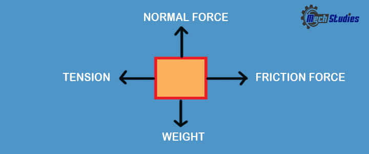
Weight:
- Any object having mass has a weight. It can be expressed in pounds or newton (N).
- If the weight is not specified, it can be computed in newton by multiplying the mass in kilograms by the gravitational constant of the Earth (9.8 m/s2).
Weight = mass x g [Gravitational accelaration, g=9.8 m/s2]
Normal Force:
- Newton’s Third Law states that every action has an equal and opposite reaction.
- This rule states that every item that is not in free fall (i.e., an object that rests on a surface) has a normal force operating on it perpendicular to the surface on which the item is resting.
- In the absence of any extra forces, the magnitude of the vertical component of the normal force equals the object’s weight.
- It is normally denoted as ‘Fn‘.
Friction Force:
- The friction force is the resistance to movement that always operates in the opposing direction of movement or prospective movement.
- It also operates perpendicular to the surface and so perpendicular to the normal force.
- Unless the opposing force reaches the maximum friction force, the friction force is equal in size to the force causing movement.
- Now, how do we calculate maximum friction force? It is computed by multiplying the normal force by the coefficient of static friction of the surface.
- It is normally denoted as ‘Ff‘.
Tension:
Have you pulled a chain or a rope by any chance? What is called the force which is imposed on these items?
This is nothing but tension, so we can say, tension means,
- The pulling force imposed on an item by a rope, chain, cable, or other similar device is referred to as tension force.
- Tension force runs from one end to the other.
- It is denoted as ‘T’
Applied Force:
- Applied force is any force that is applied to a body by a person or by some other object to cause displacement or deformation.
How to Draw a Free Body Diagram?
Let’s take an example and learn the steps required to draw and solve the problem.
Free Body Diagram Example
A 70 kg stationary metal block must be pulled up at a 45° angle by a pulley system. Consider, 0.30 is the coefficient of static friction between the incline and the metal block. Assuming no friction in the pulley system.
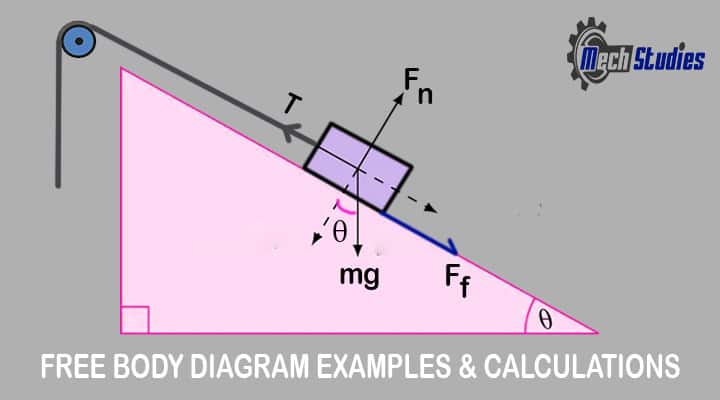
Find out the value of force in newton which should be applied to the rope for moving the metal block up the incline.
Process to Draw Free Body Diagram
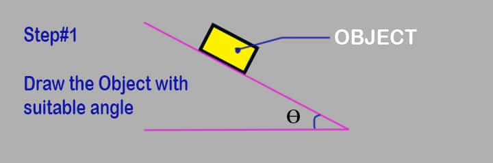
Step 1: Draw the object
Draw the object on which the force is applied without any vectors or arrows. Make sure the angle of the block should be as per requirements.
Step 2: Identification of forces
Identification of all the forces present in the system, like,
- Weight
- Normal force
- Tension
- Friction force
Let’s try to understand,
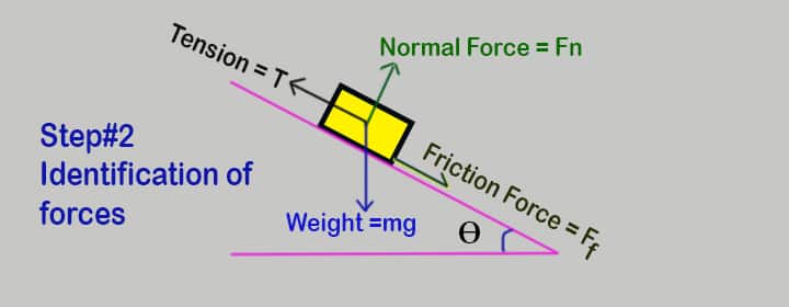
- The metal block is kept on the slope. So, the metal block has a mass then it will also have a weight that is a force. This force due to weight is acting downward.
- Since the metal block is placed on an inclined surface, there is a normal force acting perpendicular to the surface.
- The rope is attached to the metal block for pulling it, the tension is applied to the box. As the metal block is on the inclined surface, naturally it tends to move downward and this force (tension) will act opposite to downward direction.
- As the rope is attached to the metal block and is pulling up the metal block on an inclined surface, there will be a frictional force as well. This frictional force is acting on the metal block.
- This friction force will act in the opposite direction of the block’s tension that is downward towards the inclined surface.
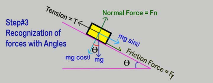
Step 3: Recognization of Forces
- All the recognized forces to be added to the block’s design.
- Need to identify their orientations in degrees with respect to the vertical or horizontal axis as defined by the geometry in the example.
Step 4: Labelling the forces
- After recognization, it is required to label all the known values of the forces.
- From the example problem above we know the value of the force applied due to the weight of the body – mass of the object (70 kg) multiplied by the gravitational constant (g=9.8 m/s2).
The free body diagram now contains all the given values and information required to solve it further.
Step 5:
Generally, the free body diagram should be reoriented so that the direction of movement is along with one of the principal axes. In the given example the entire diagram can be reoriented by rotating it 45° counter-clockwise.
Free Body Diagram Calculation
Let’s see the simple stem of the calculation for the free body diagram,
Find out the forces & equation
In order to solve the problem, we need to find the force on the rope required to pull up the metal block on an inclined surface or plane. Finding this force requires the use of an equation system.
- Although there is currently just one known variable, the weight of the body, there are three unknown variables, which require three equations. These equations define the relationship between the forces and are required to solve for each force.
- The first equation in this system provides the link between the normal force and the frictional force. Because the box won’t move unless the tension from the rope does not overcome the frictional force, the max frictional force is needed.
Normal Force & Friction Force
The max frictional force is equal to the normal force multiplied by the surface’s coefficient of static friction, which is μ = 0.30, so the first equation will be written:
Fn * μ = Ff
Where,
- Fn: Normal force
- Ff: Friction force
- μ: Coefficient of friction
Main Equation Basics
Since the question pertains to the smallest amount of force required to start moving the object, the system is in static equilibrium shortly before the time of movement. For a system in static equilibrium there are two equations taken into consideration;
∑Fx = 0 &
∑Fy = 0
It means the sum of all forces in the x-direction must be equal to zero and the sum of all forces in the y-direction must be equal to zero. Few things to be kept in mind during the development of the equations,
- Forces acting along the x-axis will only be present in the ∑Fx = 0.
- Forces acting along the y-axis will only be present in the ∑Fy = 0.
- Force in the x-axis will not be considered in the y-axis and vice versa.
Weight Component
Weight is acted toward downward, however, as the block is kept at an angle (θ=45o) the weight will be divided into two parts. The same can easily find out by trigonometric functions,
- mg cosθ [Perpendicular to plane]
- mg sinθ [Parallel to plane]
Now to get the final equations, all the forces acting on the body will be summed up together.
Force Positive & Negative
Since the positive x and y-axis were chosen in the previous stage,
- forces acting on the x-axis to the left will be negative,
- forces acting to the right will be positive.
- forces acting downward on the y axis will be negative,
- forces acting upward forces will be positive.
Force in x & y direction
According to the Free-Body Diagram, three forces work in the x-direction:
- tension,
- friction, and
- the horizontal component of weight.
Two forces will be acted in the vertical direction as per Free-Body
- normal force and
- the vertical component of the weight.
Ff = Frictional force
Fn = Normal force
T = Tension needed
Equations
Thus the final equation will be written as:-
- ∑Fx = FF + cosθ * mg – T = 0 or
- FF + cosθ *mg = T
- ∑Fy = FN – sinθ • mg = 0 or
FN = sinθ • mg
Also, FN * μ = FF
Hence, we have got two equations in the above and it is very easy to find out the unknown variables by putting the known data.
Final Result
Let’s solve it.
From the input data,
- m = 70 kg,
- g = 9.80 m/s2
- μ = 0.30
- θ = 45o
The equations are then combined to solve for tension.
- FN = sin45° • 70 • 9.81 = 0.707 • 70 • 9.81 =485.5 N
- 485.5 • 0.30 = Ff = 145.6 N
- 145.6 + cos45° • 485.5 = T
Tension, T = 145.6 + 0.707 • 485.5 = 488.2 N
Thus, in order to move the metal block up on the inclined plane, a tension force of at least 488.2 N must be applied through the rope.
Conclusion
- When the sum of all forces acting on a particle equals zero, it is said to be in equilibrium.
- While solving a problem involving an equilibrium body, develop a free-body diagram that represents all of the forces acting on the body.
- The parameters that must be met for a body to be in equilibrium are as follows:
Rx =Σ Fx = 0
Ry = Σ Fy = 0
- In three dimensions, three equations are needed to bring the body to equilibrium:
- Rx =Σ Fx = 0
- Ry = Σ Fy = 0
- Rz = Σ Fz = 0