Kaplan turbine is explained along with its basic including introduction, definition, its different components, working principle, applications, advantages, disadvantages, etc.
Let’s explore Kaplan turbine!
Kaplan Turbine
Kaplan turbine is a type of turbine used in hydroelectric plants. There were many such kinds of electric production plants but Kaplan turbine has most of the advantages over them.
- This turbine has the dexterity to work with the lower head as well as a high head or high flow rate.
- Its blade is able to shift its position automatically according to flow rate.
- This turbine has the best utilization of inputs with a very high-efficiency rate.
Why Kaplan turbine is a reaction turbine?
Kaplan turbine is known as a reaction turbine because of pressure loss. In ancient times, similar turbines were also present but they were only able to work with large water heads of water.
- Kaplan comes with the concept, to work with a low head of water flow.
- The working ability of this turbine becomes possible by making large entering area of water at blades.
- Through this technique, the blade can occupy a large volume of water to maintain the flow rate.
- In this turbine, when pressure energy converted into kinetic energy then this arrangement is known as a reaction turbine.
- The sum of kinetic energy and pressure energy is the head of the inlet of the turbine and during the flow, a part of pressure energy changes into kinetic energy.
Definition of Kaplan Turbine
Kaplan turbine is a reaction turbine that is used for low heads and requires a large quantity of water for developing a large amount of power.
- Kaplan turbine runs faster.
- High efficiency.
- It is located between the high-pressure water source and the low-pressure water exit.
In Kaplan turbine work output is occurs from turbine blades as water flows through the blades, an upward force is generated in the opposite direction of water movement. This upthrust force help in the rotation of blades.
History of Kaplan Turbine
Kaplan Turbine is the development over Francis turbine, which come into know in 1913 by Astrian professor Viktor Kaplan. It is a water turbine which contains propeller with adjustable blades.
- Professor Viktor has combined the automated propeller blades with automatic controlled wicket gates.
- This combination or improvement in Francis turbine further known as Kaplan turbine.
- It gives high rate of efficiency during high range of flow of water level.
Even though Kaplan Turbine introduced in 1912 but it takes a while to spread commercially over the industries.
Nearly 1922, Kaplan has stopped his research on this turbine due to some health issue which was further continued by Voith, and from 1924 it becomes commercially available for the industrial market.
- Voith is a group of a global technology company.
- Voith mainly works on the research of plants, products, and digital applications.
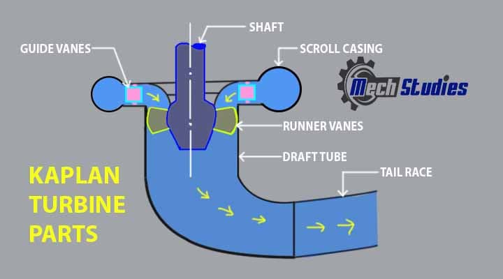
Parts of Kaplan Turbine
The main parts are as follows,
- Scroll casing
- Guide vanes
- Runner and runner blade
- Draft tube
Scroll Casing
The inlet of water in turbine starts through the scroll Casing. Scroll Casing designed in form of spiral which ensure constant flow of water along the path goes to casing.
- The cross section area of casing varies from large to narrow i.e. cross sectional area slightly decreases toward a side.
- Water that comes out from scroll Casing moves toward guide vane and after that to the runner blade.
- Scroll Casing works as protection shield for runner blade, runner and guide vane. It protects mechanical parts from external damage.
Check a nice ANIMATED VIDEO from Learn Engineering,
Guide vane
Water flows in axial direction toward runner with the help of guide vanes. Attached blades are shaped as to make the axial flow through the runner and this water become distributed in the guide vane.
- Guide vane provides smooth passage for water to flow through decreasing it’s swirl velocity.
- Guide vane used to increase the efficiency of turbine. Unusual flow of water interrupted by guide vane.
- If flow of water will be same for all time then there can be over flow problem or other mechanical damage, so guide vane used to provide on demand input. As per power requirement guide vane opens and closed, when more power output is needed them larger area will be open in result more water will enter to the blade of rotor and increases the rotational velocity. Similarly in case of less power requirement it closes it’s vane to decrease the flow velocity.
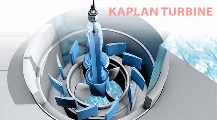
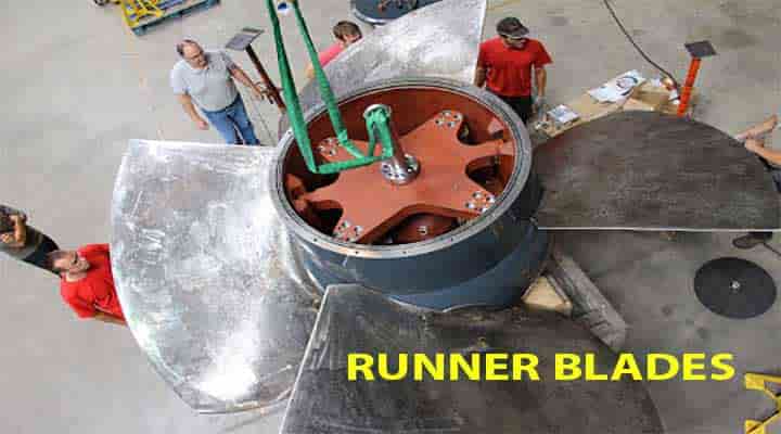
Runner and runner blade
Runner blade and guide vane had advantage that these are adjustable even through turbine is in motion.
- Runner is a rotating part which is directly connected to the generator through the shaft
- At large boss side of runner twisted blades are attached, to provide maximum output and runner can be adjusted at any particular angle.
- The twist in blade provides maximum efficiency by optimum angle of attack for every cross sectional area of blade.
Draft tube
Draft tube is a type of tube with expanding cross sectional area. It is mainly used for increasing the pressure of water leaving the runner blade.
- Every reaction turbine contains this draught tube to increase the pressure at exit side of turbine.
- At the end of turbine, the water pressure increases to come over the problem of back flow. Because at the end pressure is very low and if not being increased then back flow will occur and mechanical parts become damaged.
- Draught tube increases the pressure on the principle of converting the kinetic energy into the pressure energy.
- Draught tube has to increase the pressure at such extent that the pressure of leaving water is more than the pressure of water inside.
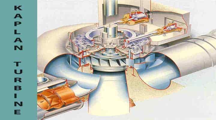
Construction of Kaplan Turbine
The turbine contains many mechanical components to carry out the turbine operation. It is necessary that the component must be in a sequential manner. In the construction of the Kaplan turbine, at the start and before entering the water into the mechanism penstock is given. Penstock connects the turbine to the casing, which is further connected with the guide vane and rotor. The turbine accommodates several rotor blades which are directly connected to the central shaft of the turbine. In Kaplan, mostly two types of blade used –
- Guide vane
- Runner blade
The general construction shall be as follows,
- Guide vane are installed with spiral casing to make the flow of water in the runner.
- Runner blades fitted with the hub and the rotation of runner blade starts due to reaction force of water which falls over the blade of runner.
- There are adjustable guide vane, which control over the flow rate. Here water turns 90 degree, due to which blades are positioned as axial to the water flow.
- The adjustable blades are attached to the shaft through the movable joints which accommodates the blade in shifting the angle for ensuring maximum efficiency of turbine for given flow rate of water.
- Blades have unique design rather than flat surface. There is slightly twisting in design of blade. Because of this twisting outer part of blade moves faster than inner part of blade.
Working Principle of Kaplan Turbine
Kaplan turbine works on the principle of axial flow reaction. So cause of this the working fluid moves across the turbine and the pressure of the turbine changes into the form of energy.
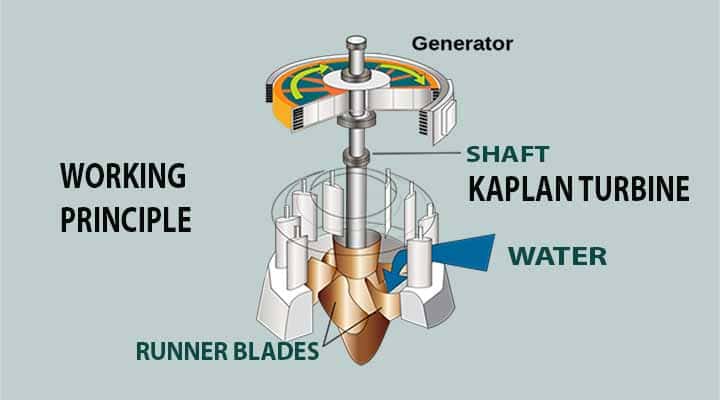
- In the system, firstly the water comes into the scroll casing through the penstock. The casing is designed in such a way that there should not be pressure loss. To reduce the pressure loss it’s necessary to maintain the flow of water and there should not be the presence of friction.
- In the further movement of the casing, water enters into the guide vane.
- Guide vanes are attached to the spiral casing.
- Water is flowing with high pressure from the casing and this pressure is maintained through rotating the runner.
- In the rotation of the runner, water losses its pressure energy and kinetic energy.
- When this flow enters the draft tube with low pressure and kinetic energy, the remaining kinetic energy gets converted into pressure energy.
- As a result, pressure energy becomes increased which utilized into further rotation of the turbine under which shaft of generator rotates and electricity produces.
Difference between Kaplan Turbine & Francis Turbine
There are a few difference between kaplan turbine and francis turbine,
| Description | Kaplan turbine | Francis turbine |
| Size | Small size & compact | Large size |
| Construction | Simple | Complex |
| Vanes | Vane ranges from 4 to 8, as compact design | Large number of vane ranges from 16 to 24 |
| Type of flow | Axial flow turbine | Normally radial flow turbine but it may be mixed flow turbine also. |
| Head | Suitable for low heads | Suitable for medium heads |
| Flow rate | High flow rate | Medium flow rate |
| Efficiency | High efficiency comparative to francis turbine | Less efficient with respect to kaplan turbine |
| Friction loss | Less | High |
| Direction of shaft | Vertical as it is axial flow turbine. | It may be vertical or horizontal based on the project |
| Governing | Governing mechanism is complex | Governing mechanism is simple |
| Specific speed | Normally it ranges from 600-1000. | Normally it ranges from 60 to 300. |
| Runner vanes | Fixed, can not be adjusted | Runner vanes are adjustable |
Application of Kaplan Turbine
There are various applications of Kaplan turbines, a few of them are as follows,
- The main and basic application of the Kaplan turbine is electricity generation.
- The efficiency of the Kaplan turbine is much higher than the other hydraulic turbines.
- It can be used for both low heads as well as a high flow rate of flow.
- Size is small comparatively.
- Construction is simple.
Advantages of Kaplan Turbine
Advantages of Kaplan turbine are as follows,
- It does not contains much mechanisms so construction is easy
- Due to less components, it does not need more space.
- It gives high efficiency rate in comparison to other turbines.
- It’s able to work with both kind of heads – low head and high flow rate also
- Rotor has 4-6 blades, which are less in compare to other turbines.
Disadvantages of Kaplan Turbine
Disadvantages of Kaplan turbine are as follows,
- Due to improper working of draft tube cavitation occurs. Cavitation is the result of back flow.
- Do not provide better efficiency with high flow rate of water.
- Cavitation problem can be solved at some extent by using stainless steel blades.
Kaplan Turbine Specification
- Nominal water flow rare in m3/s
- Specific speed
- Rotating speed in RPM
- New water jump
- Diameter of the propeller in m
- Numbers of the propeller blades
- Diameter of the hub in m
- Numbers of distributor vanes
- Size of sluic gate
- Turbine shaft material
- Turbine hub material
- Turbine blade material
- Volumetric output
- Mechanical output
- Total output
- Axial drive (maximum)
- Generated power in kW
- Efficiency of Kaplan turbine in %
High Rated Course
Intro to Fluid Mechanics for Engineering Students Part 1
Intro to Fluid Mechanics for Engineering Students Part 2

Kaplan Turbine Standards
There are many standards for turbine, a few of them are listed below,
IEC 41: 1991 -Field acceptance tests to determine the hydraulic performance of hydraulic turbines, storage pumps and pump-turbines.
IEC 193: 1965 – International code for model acceptance tests of hydraulic turbines.
IEC 308: 1970 – International code for commissioning, operation and maintenance of hydraulic turbines.
IEC 609: 1978 – Cavitation pitting evaluation in hydraulic turbines, storage pumps and pumpturbines. IEC 545: 1976 – Guide for commissioning, operation and maintenance of hydraulic turbines.
IEC 60994: 1991 – Guide for field measurement of vibrations and pulsations in hydraulic machines (turbines, storage pumps and pump turbines)
IEC 61366 – Hydraulic turbine of giving outputs higher than rated outputs to match 10% overload capability of the generators.
Conclusion
So, we have learned the basics of the Kaplan turbine along with its parts, working, etc. Please write to us, if any doubt.

Kaplan Turbine for shallow stream + or – 100cm to 60cm.
Back up electricity for battery storage from solar panels in winter ( HighestFlow )