Mohr’s circle is explained below with a brief explanation of each terminology for a better understanding of the concept. Here you will learn about the basics of Mohr’s circle, how to plot it, its uses, and its importance in advanced engineering. Let’s get started!
What is Mohr’s Circle? Definition
Mohr’s Circle Definition
Mohr’s circle is a two-dimensional graphical representation of transformation equations for plane stress.
- This graphical representation enables us to visualize the relationship between the normal and shear stresses that acts on various inclined planes at a point in a stressed body.
- It can also be used to calculate principal stresses, maximum shear stresses, and stresses on inclined planes.
This representation has been created by Otto Mohr and based on his name, the circle is named as Mohr’s circle. Let’s see the practical approach and correlation between the physical object and the cycle. In this process, a small square is considered for derivations, applications, etc. Now, what is this small square?
Considerations are as follows,
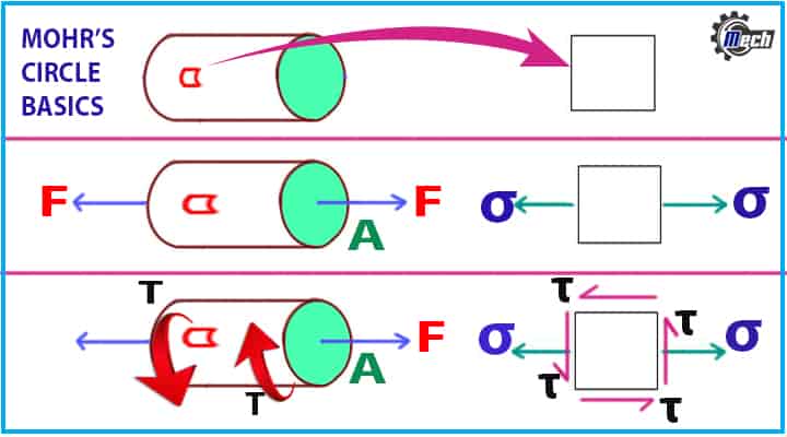
- A small square is a very small portion of the main object.
- Take a cylindrical iron rod and image a very small portion as shown in Fig. 1
- Now, if force, F is applied along the length, the entire object, as well as the small sections, will also be subjected to that force.
- So, tensile stress (σ) will be acted on the small object.
- if the iron rod is subjected to a torque, T, then a small object will also be subjected to that torque, and shear stress (τ) will be acted as shown in Fig. 1
Terminology Used for Mohr’s Circle Explanation
Principal Plane
To understand it in the simplest way, Principal Plane means a plane on which stress value normal to the plane that is normal stress value is maximum.
Normal Stress
It is the stress value perpendicular to a plane.
Principal Stress
The normal stress value in the principal plane is maximum, this stress is called principal stress.
Shear Stress
The stress acted along the plane or perpendicular to the normal stress.
Continuum
A branch of mechanics that deals with the mechanical behavior of materials is considered as a continuous mass.
Cauchy stress tensor
It is used for determining stress analysis caused by small deformations in the material bodies.
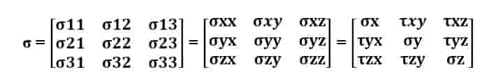
According to Cauchy stress tensor, the stress at any point in an object assumed as a continuum can be completely defined by nine stress components.
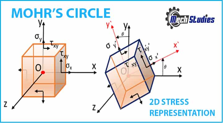
The stress distribution is determined using the coordinate system represented by (x, y) we need to calculate the stress component at point O at the new position achieved by the displacement of the object due to stress represented by (x’, y’).
To find the normal stress and the shear stress acting on a particular point, tensor transformation is performed. Mohr’s circle is the graphical representation of the transformation law for Cauchy stress tensor.
Mohr’s Circle for 2D Stress
In a two-dimensional state, three stress components namely – Normal stresses σx and σy and Shear stress τxy give the stress tensor at any given point O.
The Cauchy stress tensor can be written in a two-by-two symmetric matrix:

Our aim is to find the stress components involved using the Mohr’s circle on a rotated coordinate system i.e. (x’, y’). The rotated plane makes an angle θ with the original plane (x, y).
Mohr’s Circle Equation
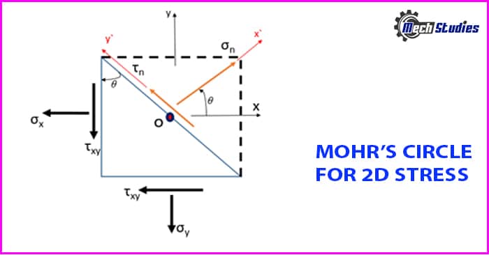
Consider a two-dimensional material element around point O with a certain unit area. Using the equilibrium forces on the given element, the magnitude of the normal stress σn and the shear stress τn can be determined by:
- σn = 1/2 (σx + σy) + 1/2 (σx – σy) cos2θ + 𝜏xy sin2θ
- 𝜏n = – 1/2 (σx – σy) sin2θ + 𝜏xy cos2θ
These equations are obtained by applying the tensor transformation law on the Cauchy stress tensor. Let’s derive the equation and find out how we get the above equations:
Stress tensor transformation law is stated as,
σ’ = AσAT
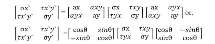
Expanding the right-hand side,
As σx’ = σn and τx’y’ = τn,
We get,
- σn = 1/2 (σx +σy) + 1/2 (σx – σy) cos2θ + 𝜏xy sin2θ
- 𝜏n = – (σx – σy) sinθ cosθ + 𝜏xy (cos2θ – sin2θ)
Where,
[cos2θ – sin2θ = cos2θ, sin2θ = 2sinθ cosθ]
The above two equations are the parametric equation of Mohr’s circle.
- 2θ = Parameter
- σn & τn = Coordinates
The points on the Mohr’s circle can be found by choosing the coordinates with σn and τn and giving the values to the parameter θ. To get the non-parametric equation of Mohr’s circle, we eliminate the parameter 2θ,
- σn = 1/2 (σx +σy) + 1/2 (σx – σy) + 𝜏xy and
- 𝜏n = – 1/2 (σx – σy) + 𝜏xy
The above equations can be rearranged into one by taking σn and τn in an equation and then squaring it:-
- [σn – 1/2 (σx +σy)]2 + 𝜏n2 = [1/2 (σx – σy)]2 + 𝜏xy2
- (σn – σavg )2 + 𝜏n2 = R2
Hence,
- R =√[(σn – σavg )2 + 𝜏n2]
- R =√[{σn – (σx +σy)/2 }2 + 𝜏n2]
Where, σavg = (σx +σy)/2
The equation of the Mohr’s circle can be given by –
(x – a)2 + (y – b)2 = r2
r = R (radius of the circle)
(a,b) = (σavg, 0) Coordinates in the (σn, τn) coordinate system.
How to Draw Mohr’s Circle?
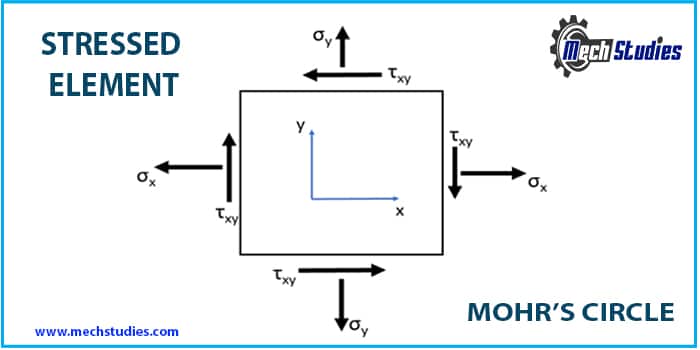
Now, after deriving the equation for Mohr’s circle let’s learn how to Draw/Plot it! To take an example we take an elastic element where the signs of the Normal stresses σx & σy are positive (Tension and stress going out of the surface) and Shear stress τxy is negative (stress coming in on the surface) as shown in the figure.
Steps needed to be followed for the construction of Mohr’s circle are given below:-
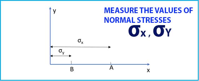
Step#1 Draw the horizontal and vertical axis (x, y).
Step#2 Measure the values of σx & σy along the horizontal (y) axis based on their sign convention and mark them as shown in Fig. 5.
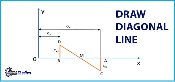
Step#3 Draw a vertical line of τxy at point C and name it as shown in Fig. 6. (Project the line up if it is positive and down if it is negative).

Step#4
- Find the midpoint between points A and B as shown in Fig. 7.
- Draw the diagonal CD passing through the midpoint M.
Step#5 Draw the circle with its centre M and passing through the points C and D as shown in Fig. 8 with its radius MC and MD.
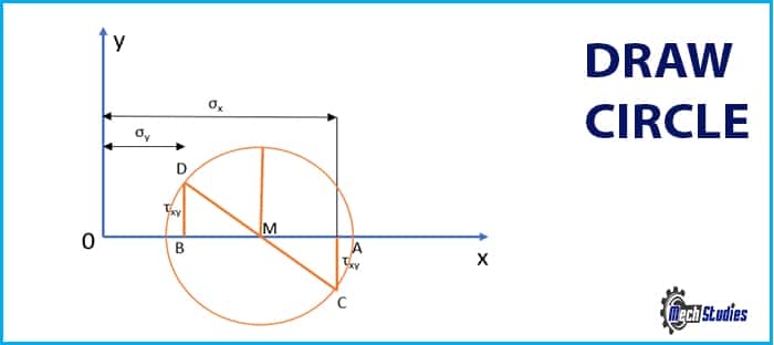
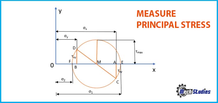
Step#6
- Mohr’s circle is ready – to get the principal stress σ1 measure OE (the maximum value)
- To get the principal stress σ2 measure OF (the minimum value) as shown in Fig. 9.
- τmax value can be found by measuring the radius of the circle.
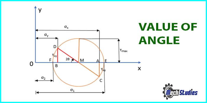
Step#7 The value of angle 2θ is shown in the Fig. 10 below.
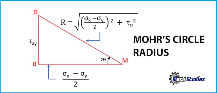
Step#8 The triangle DBM have the following elements as shown in Fig. 11:
Mohr’s Circle Example & Calculation
Now that you have learned how to draw Mohr’s circle and get the values from it. Let’s take an example to understand it better. For the below given elastic element draw Mohr circle of stress and find the maximum and minimum stress values.
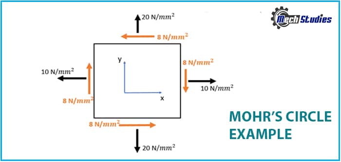
From the diagram given above we get:
- σx = 10 N/mm2
- σy = -20 N/mm2
- τxy = -8 N/mm2
Now draw the Mohr’s circle based on the values given above:-
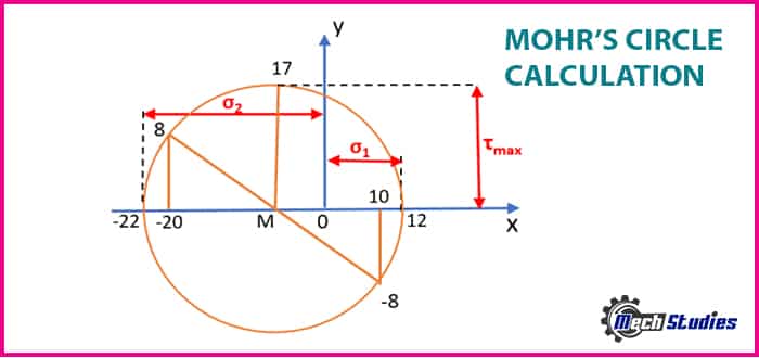
σ1 = 12 N/mm2
σ2 = -22 N/mm2
Let’s check the results using the principal stress equation:
- σ1,2 = [10 + (-20)]/2 ± √[{((10 – (-10))/2}2 + (-8)2]
- σ1,2 = – 5 ± √[(15)2 + (-8)2]
- σ1,2 = – 5 ± 17
σ1 = 12 N/mm2
σ2 = -22 N/mm2
Thus, we can see that we got the same results as we got through Mohr circle method.
Mohr’s Circle Application
Let’s see few applications,
- With advanced mechanics and the development of high-end design and analysis software, the use of Mohr’s circle to find stress at a given point has been decreasing.
- Mohr’s circle finds its use in the Structural Geology for the determination of elastic states for lithospheric stress.
- It helps to indicate the strength of different kinds of materials.
- To calculate the strength of soil, structural members, etc.
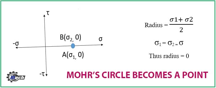
When Does a Mohr’s Circle become a Point?
- Any circle becomes a point when its radius becomes zero.
- In case of Mohr circle the radius becomes zero when the principal stresses acting on the element are same and alike. Both the normal stress should be either tensile or compressive having the same value.
- The value of shear stress should also be zero to turn Mohr’s circle in to a point.
Conclusion
We have learned all about Mohr circle in the above article, this knowledge can be used for the construction of Mohr circle with the values given and finding the principal stresses acting on it. Mohr’s circle is an easy method of finding the stress acting on a point on an elastic element with minimal calculations. Refer to a nice book on Mohr Circles, Stress Paths and Geotechnics for detail learnings. Refer to our few most interesting articles,