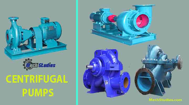
The Centrifugal pump is the most widely used pump in the world. In this article, we will learn the basic definition, parts, types, how does centrifugal pump works, various diagrams, etc. It is a rotary pump. Here, flow and pressure are generated dynamically due to rotational energy. We will learn all the basic details of the centrifugal pump in this session. One animated video is attached for visualization. Let’s explore the basics!
What is a Centrifugal Pump? Definition
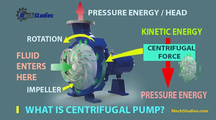
The Centrifugal pump is working based on the centrifugal force and the name follows the same. Fluid enters into the pumps, gets the energy from the centrifugal force of the impeller, and raised its velocity and pressure. Due to this pressure, the liquid is transferred from one place to another.
Centrifugal Pump Definition
A Centrifugal pump means a hydraulic machine that converts mechanical energy into hydraulic energy. A Centrifugal pump is a rotary machine that converts mechanical energy or kinetic energy into pressure energy or pressure head by means of centrifugal force, is known as a centrifugal pump. In simple understanding,
- A pump is required to transfer liquid from an area or a place to another place.
- The main acting force is centrifugal force
- Kinetic energy changed into pressure energy or pressure head.
History of Centrifugal Pump
Johann Garden first invented the centrifugal pump in 1680. However, the practical centrifugal pump was first built in 1818.
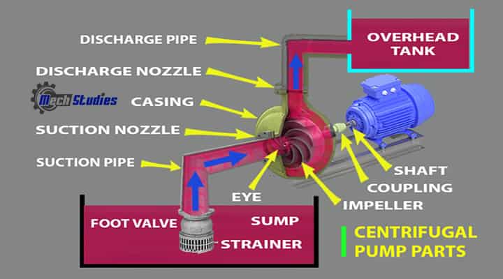
Centrifugal Pump Parts or Components including Impeller
The main parts of the Centrifugal Pump are:
| Name of Centrifugal Pump Parts | |
| 01. Impeller | 10. Coupling |
| 02. Casing | 11. Bearing |
| 03. Backplate | 12. Delivery or discharge pipe |
| 04. Suction & Discharge Nozzles | 13. Discharge valve |
| 05. Suction pipe | 14. Discharge nozzle or discharge flange |
| 06. A foot valve | 15. Mechanical seal |
| 07. Strainer | 16. Shroud and Legs |
| 08. Suction nozzle or suction flange | 17. Adaptor |
| 09. Pump Shaft / Connections |
Centrifugal Pump Impeller
The impeller is the main part of the pump and it is connected to a motor drive shaft that drives the pump. The impeller rotates based on the rotation of the motor. Pumps can also be driven by other drivers such as,
- Natural gas engines or
- Diesel engines or
- Steam turbines.
The impeller is fixed onto the pump shaft which is housed in a pump casing and backplate
- The impeller transfers energy from the motor to the fluid which is to be pumped.
- Due to the rotation of the impeller, fluid get accelerations and
- increase velocity as well as kinematic energy.
Impellers have a lot of vanes. These vanes help the liquid to flow from the center to the outer edge of the impeller. There are three basic impeller designs
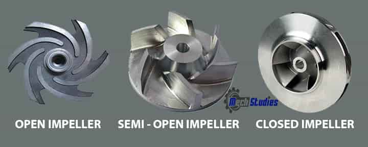
Open Impellers
- Open impeller means vanes are open on both sides. Since it is open, vanes don’t have any support from any side.
- This kind of impeller handles less amount of water and the pumps are smaller and efficiency is less.
- This impeller can handle suspended solids.
Semi-open Impellers
- In this impeller, vanes are semi-open, which means only one side is open.
- Here, vanes are attached or supported with a single plate. Since the liquid is interacting with the rest of the liquid inside the pumps, these are less efficient.
- However, it is better than an open impeller and can handle suspended solids and viscous fluids.
Closed Impellers
- Here, no side of the impeller is open, which means both sides are closed.
- It is looking like a “sandwiched” panel. The liquid travels thru the vanes or channels among the impeller and plates.
- This is the most efficient impellers. These kinds of impellers are mainly used for clear liquids.
Pump Casing
Centrifugal pump casing is simply like an airtight passage. This is housed the pump impeller and helped to convert the kinetic energy of the impeller into the pressure head. There are three different kinds of centrifugal pump casings:
- Volute casing
- Vortex casing
- Casing with guide blade
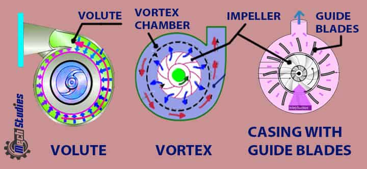
Volute casing
The volute casing is a spiral passage area between the impeller and casing to increase the area gradually towards the delivery pipe.
- We know, if the area is increased, then the flow will decrease naturally.
- Flow decrease means, velocity, as well as kinetic energy (K.E), will decrease.
- This reduced velocity or K.E converts into pressure energy and increases the pressure energy or pressure head in the casing.
- The volute casing will increase the efficiency
- Loss is more because of Eddie formation
The volute casing is two types based on design,
- Single volute casing (Only one volute)
- Double volute casing (Two volutes)
Vortex casing
Vortex casing means a round or circular chamber between the impeller and casing.
- Due to the circular chamber, the eddy loss, as well as energy loss, is very less
- Vortex casing is more efficient than the volute casing.
Casing with guide blades
As the name implies, in this kind of casing, the impeller is surrounded by a number of guide blades.
- These blades act as diffusers.
- The diffuser means a gradual increase in flow area, which reduces velocity or K.E and increases pressure energy.
Backplate
The backplate is of pressed steel or any rigid material, based on application. This backplate and pump casing together form an actual pump liquid chamber where the fluid is undergoing the process.
Suction Nozzle & Discharge Nozzle
- Suction Nozzle is provided for fluid intake
- The axis of the suction nozzle corresponds to the impeller’s rotational axis.
- Discharge nozzle is provided for fluid outlet
- The discharge nozzle is at the normal to the axis of the impeller.
Suction Pipe with a foot valve and strainer
The suction pipe means the pipe at the suction side. It connects between the pump enclosed area and the water sump. One end of this pipe is connected to the center of the impeller or the inlet of the pump which is known as the eye and another end dips into the water which is to be lifted.
- In the case of double end suction, the pump consists of two suction pipe which is connected to the eye from both sides.
- A foot valve normally fitted with a strainer at the lower end of the suction pipe.
- This valve acts as a check valve which allows liquid only in one way that is the upward direction.
- The strainer filtrate unwanted particle from the water and prevent the centrifugal pump from blockages.
Pump Shaft / Connections
It is a shaft that connects the motor and impeller. Most pumps have stub shafts. Stab shaft means it is fixed to the motor shafts with the help of couplings.

- Simple design
- Less vibration and noise
Coupling
The coupling is an important part to connect the pump with the motor if it is not directly driven.
- It transfers power from driver to driven machine
- It helps to easy servicing
- If the coupling is flexible, it helps to protect the bearing
- It can adjust a small degree of misalignment

Bearings
The pump consists of rotating and stationary parts. Bearings are used to make a correct alignment between these two,
- Bearings support all the loads created by the rotating parts.
- It helps to keep the shaft deflections within acceptable limits.
- It helps to transmit the load to the pump foundation.
Delivery pipe & Valve
The delivery pipe helps the pump to deliver liquid from the pump outlet to the required level.
- It makes the connection between the pump outlet to the deliver point
- A valve is provided near the outlet of the pump on the delivery pipe to control the controls the flow from the pump.
- The non-return valve is the type as the delivery valve.
Mechanical Seal
The pump shaft or motor shaft is connected to the impeller. The impeller is kept inside the casing. Hence, it is mandatory,
- to seal the shaft entry portion into the pump casing. This sealing is known as a mechanical seal &
- it helps to prevent any kind of leakage.
Shroud and Legs
Many pumps are fitted with shrouds, adjustable legs. The shroud helps to minimize the noise level and both these things help to protect the motor against damage.
Adaptor
Most pumps are driven by the motor. Now, the adaptor connects the motor and the pump. In the case of direct coupling, there will not be any adopters.
Types of Centrifugal Pumps
Centrifugal pumps are classified into many types depending on the following factors:
- Number of impellers or numbers of the stage,
- Impeller design,
- The orientation of case-split,
- Type of volute
- Bearing support,
- Shaft orientation
- Miscellaneous centrifugal pumps
- Based on API 610 standards
Centrifugal Pump Types Based on the number of impellers
Single-stage centrifugal pump
A single-stage pump means a single impeller in the pump.
- This pump is having the simplest design
- Maintenance is very easy
- Suitable for low-pressure and large flow rates applications.
Two-stage centrifugal pump
- A two-stage pump means two impellers in the pump.
- In the case of medium head applications, these two-stage pumps are widely used.
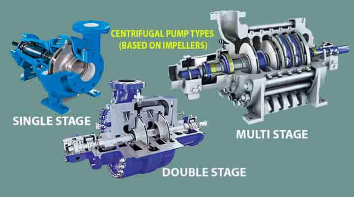
Multi-stage centrifugal pump
- A multi-stage pump means three or more impellers in a pump.
- These are mainly used for high head services.
- In this case, many impellers are connected in series to get the required head.
Centrifugal Pump Types Based on the type of impeller design
Single suction Pump
Single suction means as the name signifies one-sided suction of the impeller. In this pump, liquid enters in the impeller through one suction pipe only.
- It has a single-suction impeller
- Liquid enters through one side only
- Simple design
- This pump can have higher axial thrust due to an imbalance of flow coming in only one side.
Double suction Pump
When the flow required is very high, a single suction pump cannot be fulfilled the requirements.
- In this case, liquid enters in the impeller through both sides of the impeller and increases the flow.
- Normally, split-case pumps are the most widely used pump with double suction impeller.
Centrifugal Pump Types Based on the orientation of case-split
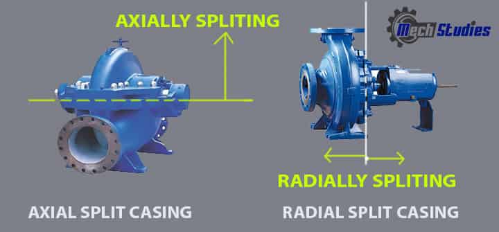
Axial split Pump
As the name signifies, axial split, these kinds of pumps, split axially. Here,
- Casing splits axially.
- The line which splits the pump will be at the centerline of the shaft.
- Axial Split Pumps are generally mounted horizontally for easy installation and maintenance.
- These pumps are widely used in Oil Refineries
Radial split Pump
- Radial split pump, as the name suggests, casing splits radially.
- In this pump, the split line is perpendicular to the shaft center-line.
- It is simply the way to open a pump for any maintenance.
Centrifugal Pump Types Based on the type of volute
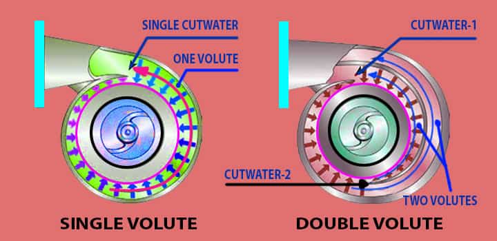
Single volute Pump
This kind of pump has one volute, which means a single volute. These are with low capacities and size is very small.
- If the space is very small and the capacity requirement is less, this kind of pump is suitable.
- A single volute pump has higher unbalancing radial loads.
Double volute Pump
This kind of pump has two partial volutes. At 180 degrees apart, both the volutes are located.
- Due to this 180-degree angle, the pump has a balanced radial load.
- Double volute centrifugal pumps are widely used in many industries.
Centrifugal Pump Types Based on where the bearing support
Overhung
We know the impeller is fitted with the shaft and supported. In these kinds of pumps,
- The impeller is mounted at the end of the shaft.
- This shaft is supported by bearings at only one side instead of both ends.
- These pumps can be horizontally or vertically oriented.
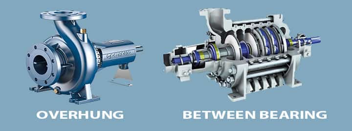
Between-bearing
- Between bearing means, the shaft is supported by bearings at both ends.
- Here, the impeller is located between the bearings.
Based on shaft orientation
Horizontal Pump
In this kind of pump, shafts are in a horizontal plane and due to this orientation, these pumps are known as horizontal centrifugal pumps. Servicing and maintenance are very easy in this kind of pump.
Vertical Pump
- A vertical centrifugal pump means shafts will be in a vertical plane.
- Overhung Pumps, radial-split case type pumps are this kind of pumps.
- Borewell pumps, sump pumps are some examples of this kind.
Other centrifugal pumps
Canned motor pump
| Canned Pump | Characteristics |
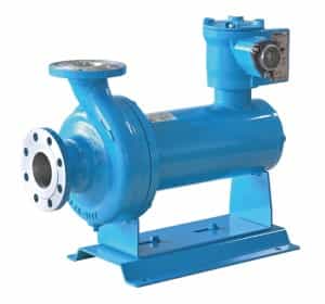 | This pump is a compact and the motor is an integral part It combines the impeller and motor with a common shaft. The motor is basically hermetically sealed No shaft seal is used, and it is called seal less or seal less. In this type of pump, the rotor winding is encapsulated in a ‘can’ The drive shaft up to the impeller is wetted in the fluid to be pumped If any problem in the motor, entire pumps to be replaced. |
In many chemical industries, or hydrocarbons applications, or toxic, dangerous liquid handlings, where the leakage is not permitted, canned motor pumps are used.
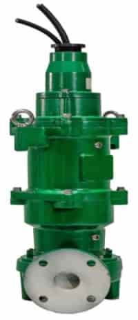
Magnetic drive pump
| Magnetic drive pump | Characteristics |
 | Compact but motor is not an integral part The pump rotating shaft and the motor is magnetically coupled. No shaft seal is required due to the magnetic drive. It is also used where leakage is an issue |
Chopper pump
| Chopper pump | Characteristics |
 | To chop or maceration of solids present in the liquid The impeller is having teeth for chopping Food processing. Chemical industries, sewerage, etc. widely used |
Grinder pump
| Grinder pump | Characteristics |
 | It is used to grind the debris in the wastewater drainage system. |
Circulating or circulator pumps
- Used to circulate liquids or slurries.
- Working in a closed-loop normally.
- Widely used in HVAC, fire fighting system, etc. system.
Cryogenic pump
| Cryogenic pump | Characteristics |
 | These are used for handling liquefied natural gas, Liquid oxygen, liquid nitrogen, coolants, are handled by this kind of pumps It is also used for pumping liquid from one capacity to another. It is a vacuum pump and condenses the vapours or gases. Suitable for very low temperature as well |
Trash pump
| Trash pump | Characteristics |
 | These are simple portable pumps Widely used for dewatering requirements Normally used to transfer the water with hard and soft solids such as mud, etc. |
Slurry pump
| Slurry pump | Characteristics |
 | It is used to transfer slurry Very rigid construction Used in mining or power plants industries Highly abrasive slurries are well handled |
Centrifugal Pump types based on API 610
API 610 standard is the most common centrifugal pump standard used in petroleum industries. It is further classified,
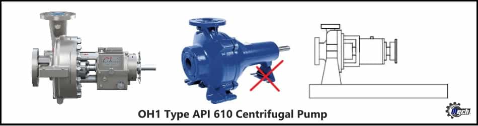
OH1 Type Pump
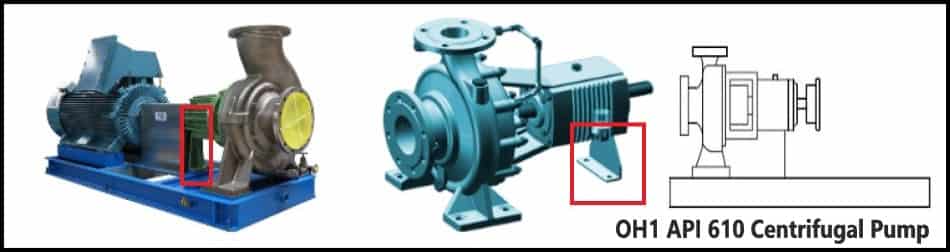
- It is an overhang 1 type pump
- This pump is a single-stage pump.
- Foot-mounted.
- Horizontal pump
- With flexible coupling.
- Leg supports at the opposite end of the suction.
OH2 Type Pump
- Overhung, centreline supported.
- No leg support at the bearing end with respect to OH1
- Single-stage end-suction
- Single bearing housing.
- Bearing housing absorbs the force imposed on the shaft.
- Bearing housing helps to the proper position of the impeller during the operation.
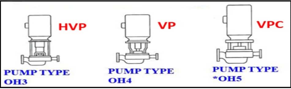
OH3 Type Pump
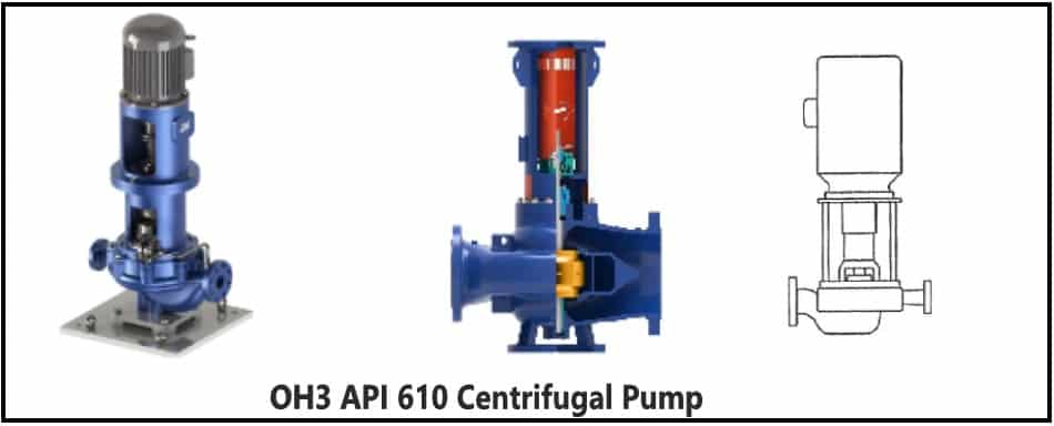
- Single-stage.
- Overhung.
- Flexible coupled.
- In-line pump with an overhung impeller.
- Flexible coupling.
- Separate bearing bracket with integral bearing housing.
- Bearing housing helps in absorbing pump load.
- The motor is directly mounted.
OH4 Type Pump
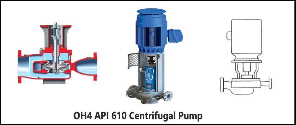
- OH4 (Overhung) type pump is flexibly coupled single-stage.
- In-line pump with overhung impeller
- Rigid coupling, this is the difference between OH3 & OH4
- Separate bearing bracket with integral bearing housing.
- Bearing housing helps in absorbing pump load.
- Motor directly mounted.
OH5 Type Pump
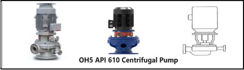
- OH5 (Overhung) type pump is a closed coupled pump.
- The pump impeller is directly attached to a driver.
- Vertical pump.
- In-line.
- Single-stage pump.
OH6 Type Pump
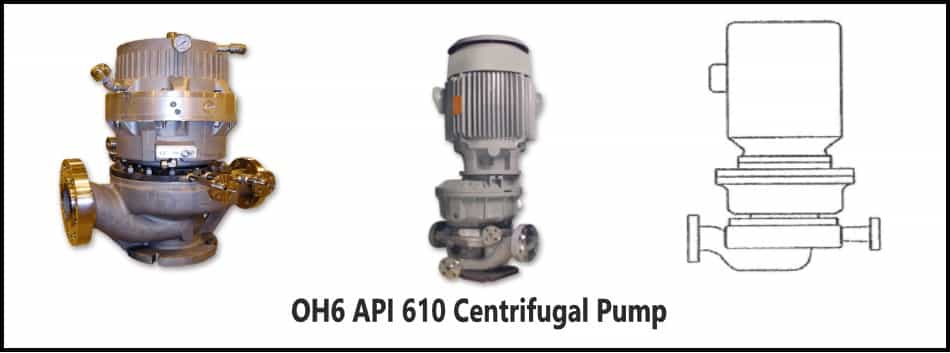
- High-speed pump.
- It has a speed-increasing gearbox.
- The impeller is directly mounted on the gear shaft.
- Flexible coupling.
- Single-stage overhung pump
- Suitable for vertical and horizontal installation.
BB1 Type Pump
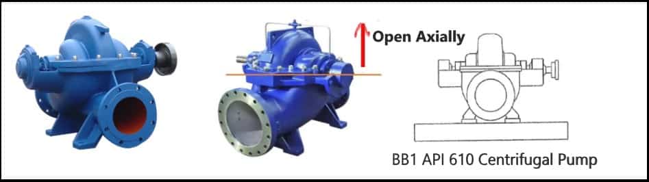
- Between bearing 1 type,
- Horizontal and one-stage or two-stage pump.
- Axially split type.
BB2 Type Pump
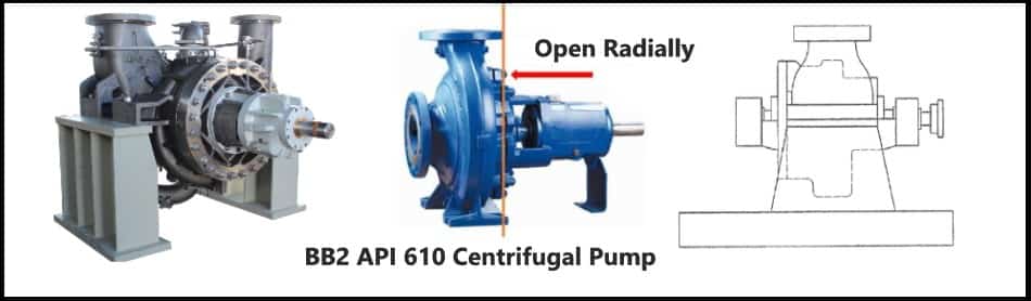
- BB2 (Between Bearing) is a horizontal and one or two-stage pump.
- Radially split type.
BB3 Type Pump
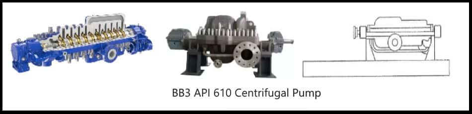
- BB2 pump is multistage pumps
- Axially Split type
- The flexible coupling is used to connect the drive.
BB4 Type Pump
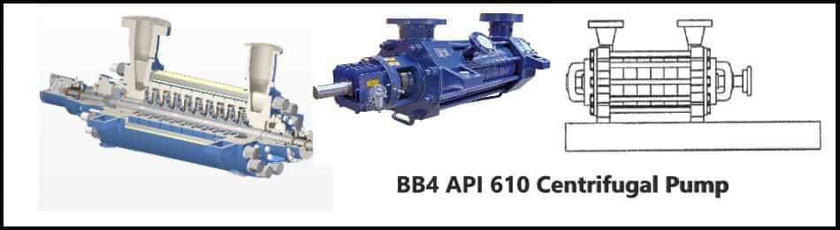
- BB4 pump is Multistage pumps
- Each stage of BB4 is like a ring
- All rings are connected together by tie rode around them, known as ring section pump
- Radially split design
- Installed on the shaft supported by bearings at both ends.
BB5 Type Pump
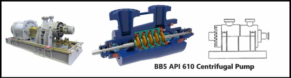
- BB5 pump is a multistage pump.
- Double casing
- Radially split design
- Flexible coupling
- Barrel like design and known as Barrel Pumps.
- High-pressure applications.
VS1 Type Pump
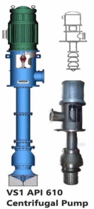
- This kind of pump is a single casing and vertically suspended type.
- Mainly used as wet pit pumps or diffuser pumps.
- The column is used as discharge.
VS2 Type Pump
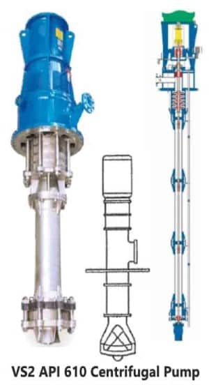
- This kind of pump is a volute casing type.
- This is a vertically suspended type.
- Mainly used as wet pit pumps or diffuser pumps.
- The column is used to discharge.
VS3 Type Pump
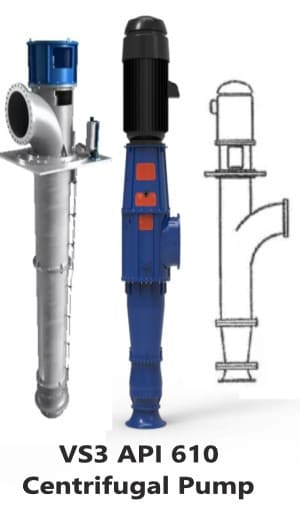
- These pumps are axial flow type,
- Single casing
- Vertically suspended.
- The pump assembly is mounted on a column, this column is used for discharge.
VS4 Type Pump
- VS4 pump has a separate discharge column.
- Volute casing design.
- Vertically suspended shaft.
- It can be supported through intermediate bearings.
VS5 Type Pump
- VS5 pump like VS4 also has a separate discharge column.
- The difference is in the vertically suspended shaft.
- No intermediate bearings.
- The pump shaft is a cantilever and supported by a top bearing.
VS6 Type Pump
- Double casing.
- Vertically suspended and “Can” type pump.
- The pump column is used to discharge
- Increase NPSH by installing a pump underground.
VS7 Type Pump
VS7 type pump uses a volute casing design as compared to VS6.
How Does Centrifugal Pump Work? Diagram
Centrifugal Pump Working Basics
If a certain quantity of liquid is forced to rotate by an external torque, the pressure head of the liquid will increase. This increase is because of forced vortex flow. The rise in pressure head at any point is directly proportional to the square of the tangential velocity at that point. Hence, based on Bernoulli’s theory, we can say the pressure head is v2/2g.
Where,
- V = velocity
- G = gravitation acceleration
So, we can conclude that, if the area is more then velocity is more, velocity more means kinetic energy more which changed into pressure head. Due to this pressure head, the liquid can be lifted to a different level.
How does a centrifugal pump work with Diagram
Below the schematic diagram of the centrifugal pump explains step by step working of the pump.
Step#1 Priming & Start-up: Do you have to prime a centrifugal pump? Let’s try to understand! Centrifugal Pump doesn’t suck the liquid, and priming is to be done at the beginning. Priming means liquid must be filled-up in the suction pipe to fill all the air gaps.
If air is not removed from the pump, then a small negative pressure will be created at the suction pipe and it cannot suck the water from the water sump or reservoir.
- Priming means filling the liquid in the suction pipe.
- The priming is done by a “Foot Valve” installed at the end of the suction pipe.
- The filling is done up to the pump casing top.
In a centrifugal pump, the discharge pressure is directly proportional to the density of fluid and priming is necessary.
Step#2 Start the motor: Once priming is done, the motor to be switched on. When the motor or drive shaft rotates, the impeller also rotates since both these are connected.
The suction pipe is connected between the water sump and the eye. When the impeller rotates at high speed, water will also start to rotate at the same speed and the impeller accelerates the fluid out through the impeller vanes. Now, whatever the type of impeller, it may be closed or open or semi-open, the principle is the same.
Step#3 Suction: Due to rotation, a negative pressure is created in front of the impeller and a vacuum is created. Water will start to fill these vacuum and water will flow continuously. If the pressure reduces to below the vapor pressure, the bubble formed which is not recommended to avert cavitation, which damages the impeller.
Step#4 Increase in Pressure Energy: There are two important design parameter volute and diffuser, that plays an important role.
- When the impeller rotates, the liquid also rotates with the impeller and the centrifugal force is acted on the liquid.
- The velocity and pressure are transferred to the liquid during this process.
- This liquid then enters inside the pump volute casing (sometimes with diffuser)
- The volute casing is looking like a curved funnel and the cross-sectional area is gradually increased.
- Reduction in the area reduces the velocity of the liquid.
- This velocity reduction converted into pressure and pressure is increased.
- This liquid then passes towards the discharge nozzle.
The purpose of both types of designs is mainly to translate the fluid flow into a controlled discharge at the required pressure. In this design, velocity is reduced and converted into pressure energy as per Bernoulli’s theory. Hence, pressure energy or pressure heat at the outlet is increased.
In the case of the diffuser, since the liquid is expelled between stationary vanes, the velocity of the liquid is reduced and the same is converted into pressure energy. Hence, a high-pressure head is developed. The work done, head, efficiency calculation of centrifugal pump are clearly captured along with velocity triangle in a separate article.
Factors that Impact Centrifugal Pump Performance
- Suction Pressure – If pressure at pump suction is less than required, cavitation will occur and the impeller will be damaged
- Flow at suction – Constant flow at pump suction is required, otherwise the pump cannot work at design conditions.
- The viscosity of the fluid – Best for lower viscosity
- Vapor Pressure of the Fluid – Very low-pressure liquid is not suitable, it will make cavitation.
- The density of the fluid – High-density liquid is not suitable.
Main features of the Centrifugal Pump
The main feature of centrifugal pumps is:
- Centrifugal pumps are used for higher flows and in case of low viscosity or low viscous liquids. It can handle liquid around 0.1cP as well.
- In some chemical industries, most of the pumps are centrifugal pumps.
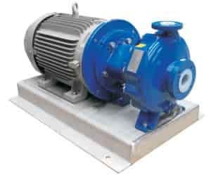
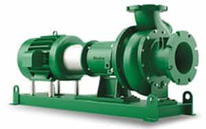
Typical Centrifugal Pump Package
Let’s see what are the basic components in a standard pump package. The components are,
- Pump along with casing, impeller, shaft, etc.
- Sealing system
- Gland packing system
- Motor
- Baseframe
- Coupling
- Valves
- Pipes
- Pipe header
- Pressure gauge
- Temperature gauge
- Pressure transmitter
- Temperature transmitter
- Flowmeter
- Cooling system
- Control system
- Cablings etc.
How to Select a Centrifugal Pump?
We have got a basic idea about the centrifugal pump, now, how to select this kind of pump and what are the main criteria needs to look into? Let’s see the main factors for this type of pump selection,
Viscosity
- We have already learned that centrifugal pump is suitable for low viscosity. Now, if you are working in a project, where you need to handle low viscous liquid, then centrifugal pump will be your option.
Pressure/Head Requirements
- Check the pressure / head requirements for the applications.
- In case of very high pressure, proper sealing to be used.
Temperature requirements
- In case of high temperature applications, proper cooling/suitable gaskets, sealing etc. should be taken care
Density of fluid
- Normally, we have considered water as working fluid, however, it can be any other fluid as well. Hence, density as well as specific density or specific gravity to be considered.
Differences between Centrifugal Pump and Positive Displacement Pump
We have god a basic idea about centrifugal pumps. Now, do you know what are the differences between centrifugal pumps and positive displacement pumps? Let’s explore!
| Parameters | Centrifugal Pump | Positive Displacement Pump |
| Overview | Fluid enters into the pumps, gets the energy from the centrifugal force of the impeller, and raised its velocity and pressure. | In the positive displacement pump, the piston or plunger moves forward & backward stroke, and mechanical energy is converted into hydraulic energy. |
| Working principle | The main working principle is associated with centrifugal force | Mainly reciprocating action or rotary or diaphragm action. |
| Creation of Suction lift | This pump is not able to create a vacuum as well as a suction lift. | This pump creates a vacuum as well as a suction lift. |
| Performance | In this type of pump, pressure is changed with a change in flow rate. | In this type of pump, pressure is not changed with a change in flow rate. |
| Priming | It is required. However, there is one type of centrifugal pump, called self-priming pump, which doesn’t require priming. | In case of a positive displacement pump, priming is not required. |
| Type of flow | It gives constant flow. | It gives pulsating flow. |
| Shear sensitive fluids | High-speed centrifugal pump damages shear-sensitive fluids like slurries, foodstuffs, emulsions, etc. | These pumps are suitable for shear-sensitive fluids like slurries, foodstuffs, emulsions, etc. |
| Efficiency vs pressure | In case of optimal pressure range, its efficiency is high. However, it decreases at high and low pressures. | Efficiency increases with increasing pressure |
| Efficiency vs viscosity | With the increase of viscosity, the efficiency of the centrifugal pump decreases. | With the increase of viscosity, the efficiency of the centrifugal pump increases. |
| Application | It is applicable for high flow or capacity & medium or low head. | It is applicable for low capacity & high Head. |
Centrifugal Pump Application
- These pumps are widely used for pumping water, other low & medium viscous liquids.
- Solvents, acids, bases, oils, organics, etc. are easily handled.
- Water supply in buildings, domestic water supply, many industries.
- Pumping sewage and slurries.
- Fire protection system
- The beverage industry, like transferring juice, bottled water, etc.
- Dairy industries, like transferring milk, etc.
- Manufacturing industries
- Chemicals industries
- Pharmaceutical industries
- Food Production
- Aerospace
- Refrigeration and air conditioning industries
- Oil & gas industries – pumping crude oil, slurry, etc.
Centrifugal Pump Advantages
- Simple & compact design
- Weight saving
- Less capital cost & operating cost
- Less space requirements
- Less moving parts & easy for maintenance
- Less capital cost
- Steady & consistent flow
- Handles a large volume of liquids
- These pumps do not include drive seals that reduce leakage risk.
- These pumps are used to pump out normal liquid to harmful and risky fluids as well.
- These pumps handle non-viscous, and low viscous to medium viscous liquids.
- These pumps generate low friction, hence, friction loss is less.
- Highly efficient
- Normally, the motor and pump are separated, heat transfer is negligible.
- Cost is comparatively less
- Installation is easy
- Noise is very less
- Very less wear & tear with respect to other kinds of pumps.
- The pressure is uniform.
- No shock waves or pulsation.
Centrifugal Pump Disadvantages
What are the limitations of a centrifugal pump?
- It uses impeller rotation for suction, hence, very less suction power.
- Due to the low suction power, priming is necessary.
- The coupling can generate some magnetic resistance, which can make energy losses.
- Once the intense load occurs, possibilities are there for the coupling fall.
- Efficiency reduces when this pump handles high viscous liquids.
- Very less flow can overheat the pump.
- Not suitable for high head applications.
- It can produce cavitation, corrosion, etc.
What are the Real Problems of Centrifugal Pumps?
We have got the basic idea of the centrifugal pump disadvantages, now let’s see the real problems,
Cavitation: Cavitation is one of the most critical problems in a centrifugal pump. If the net positive suction head becomes very low then vapor will be formed at the suction of the pump, which results in the cavitation. It damages the impeller as well as the internal parts of the pump.
Priming: Priming is essential for centrifugal pumps except for self-priming pumps. If priming is not done properly, the pump will not work.
Corrosion: Pump material has to be selected based on the type of fluids to be handled by the pump. Wrong selection, will result in corrosion of the pump internal parts due to the properties of the fluid which will be pumped.
Pressure: Centrifugal pump is not suitable for very high pressure or very low-pressure application. Hence, it should be kept in mind during pump selection.
Wear: Due to suspended solids, there may be a chance of wear of the impeller. If there is cavitation in the pump, the impeller may also undergo wear.
Sealing or Packing: The shaft is rotating and it is sealed properly so that there will not be any possibilities of leakage of fluid. If there is any problem with sealing, fluid will be leaked and come out.
Clogging: In this type of pump, handling liquids with large debris or particles can clog the pump.
Low Flow: In case, centrifugal is running with a very low flow, then it will start to be heated which results in overheating.
Centrifugal Pump Safety
There are a few key points for centrifugal pump safety:
- At first selection of pump. It should be based on the application.
- Always check the overheating of the pumps.
- Follow the instruction manual, as well as the operator, should have proper training.
- Internal parts shall be maintained, and worn-out components shall be replaced immediately.
- The blockage of the suction and discharge line shall be checked.
- Air leaks shall be checked.
- Check for Air Leaks.
- Never skip routine maintenance and scheduled inspection.
- A shut-off test shall be done.
- Proper location and proper maintenance space should be considered.
Standards for Centrifugal Pumps
A few of the major codes and standards that are used in process industries are listed below:
ANSI B 73.1 – Horizontal End Suction
Centrifugal PumpsANSI B 73.2 – Vertical In-Line Centrifugal
PumpsANSI B 73.2 – Sealless Horizontal End
Suction Centrifugal PumpsAPI 610 – Centrifugal Pumps
BS 5257 – Specification for horizontal end-suction centrifugal pumps (16 bar)
ISO 2858 – End Suction Centrifugal Pumps
ISO 5199 – Centrifugal Pumps
Manufacturers of Centrifugal Pumps
There are so many manufacturers available across the world, few of them are illustrated below,
- Flowserve
- KSB Group
- Grundfos.
- Sulzer.
- Schlumberger
- ITT Inc.
- Ebara, etc.
Centrifugal Pump Video Tutorial
Refer a very nice video tutorial explain this pump in details. Its cheap and worth.
Conclusion
Hence, we have got a basic idea about the centrifugal pump, its parts, working principle, etc. Any questions, please write to us. Refer Our YouTube MechStudies – YouTube
Keep functioning ,splendid job!
It’s great that you talked about how the centrifugal pump is the most widely used pump in the world. I was watching a video about pumps last night and I learned about the use of centrifugal pumps. One of the examples I saw was the ANSI centrifugal pump, which looks very useful.
https://www.truflo.com/ansi-pumps/