Rankine cycle is explained along with T-s, P-v, diagrams, reheat, equation, etc. All the formulas and examples are well captured to have a basic idea. This is basic thermodynamic cycle on which heat engine works and it helps to extract heat from a fluid between a heat source and sink. It is named based on the William John Macquorn Rankine. The best application of Rankine cycle is the thermal power plant where thermal energy from fuel is transformed into electricity with the help of this cycle.
What is Rankine Cycle? Basics & Definition
Let’s learn the learn Rankine cycle with basic, definition, history.
Rankine Cycle Basics
The Rankine cycle is one of the popular cycles widely used by power plants. It is used to convert the pressure energy coming from the steam to mechanical energy with the help of steam turbines.
- The Rankine cycle is a kind of ideal cycle that described the process by which the heat engines or steam engines allow work to be extracted from the fluid such as steam in steam power plants.
- The heat sources from which the power plant uses the Rankine cycle are coal, natural gas, or oil.
Why it is named as Rankine Cycle?
The Rankine cycle is named after the William John Macquorn Rankine professor at Glasgow University.
Rankine Cycle Definition
It is defined as a cycle, where heat energy is supplied to the system via the boiler where the fluid typically water is converted to high pressurized steam, and the steam is passed over the turbine and the work is generated.
The friction losses and others are neglected in the ideal Rankine cycle to for simplification of the calculation.
- If you know the typical power plant cycle to generate work with the help of a turbine it will be easy to understand the Rankine cycle.
- The cycle efficiency is limited by the high rate of vaporization.
- The cycle works in a closed-loop as the fluid will be reused again.
So, we will see a typical ideal Rankine cycle its processes, and some of its variations. Also, what changes are there when we compare the ideal with the real cycle? Also check if you are you thinking to explore Solar Products ?
?
Rankine Cycle Diagram & Components
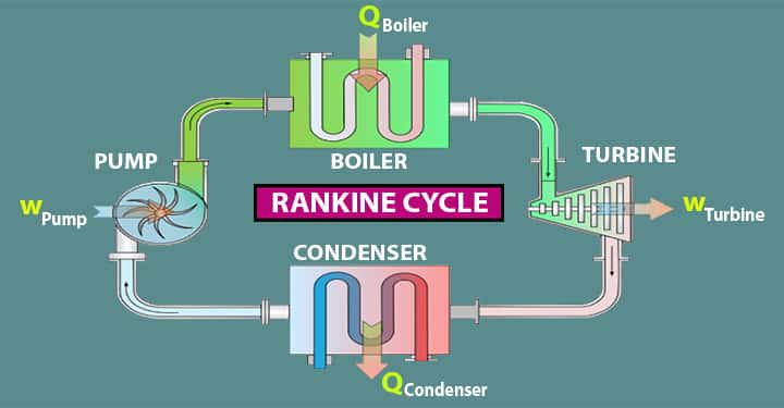
Let’s see the diagram of the Rankine cycle and its main components.
There are four main components,
Rankine Cycle Component#1 Pump
- Point 1-2 indicates pump in Rankine cycle
- Work done incurs to the system.
- Pressure is increased in this stage.
Rankine Cycle Component#2 Boiler
- Point 2-3 represents the boiler in the cycle.
- Heat is added to the high pressured fluid by the boiler.
- Temperature is increased up to a boiling point.
- Water changed into vapor as its phase is changed.
Rankine Cycle Component#3 Turbine
- Point 3-4 indicates the turbine in the Rankine cycle diagram.
- Expansion of vapor happens in the turbine.
Rankine Cycle Component#4 Condenser
- Point 4-1 indicates the condenser.
- Waste heat is removed from the condenser with the help of the condensation process.
Ideal Rankine Cycle Processes with T-S & P-v
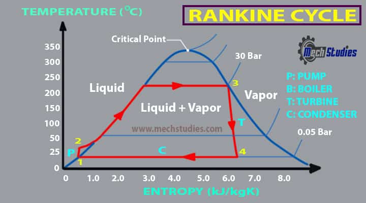
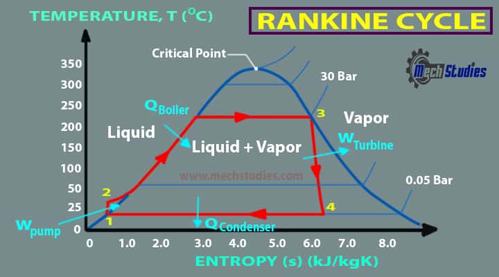
In the ideal Rankine cycle, there are four processes running, we will check each of them and what will happen in each process. It can be understood with the help of the T-S diagram better.
In case of the process 1 -2 – Isentropic compression
In this process, the working fluid will be pumped from low pressure to high pressure. The fluid is in the liquid form at the start of this process. The water is heated to the saturation temperature, keeping the entropy constant.
Process 2-3 – Constant Pressure Heat Addition Process in Boiler
In case of this process, the high-pressure liquid will enter the boiler. The fluid will be heated at constant pressure with the help of an external heat source and it will become a dry saturated vapor. The required energy needed for heating up can be calculated with the help of an enthalpy entropy chart or steam tables.
Process 3-4 – Isentropic Expansion Process
The dry saturated vapor at the end of the process 2-3 will be expanded through the turbine in this process. It will generate the power. Due to expansion the temperature and the pressure of the vapor will be decreased. Same as the above the output can be easily calculated.
Process 4-1 – Constant Pressure Heat Rejection in Condenser
At this process, the low temperature and low-pressure vapor will be condensed in the condenser. It will be converted into saturated liquid. So, these are the four processes in the ideal Rankine cycle.
- In case of the ideal Rankine cycle, the pump and turbine would be isentropic so, they will be generating maximum network output while generating no entropy.
- If you can see in the above image the process 1-2 and 3-4 are shown via the vertical lines. They are like a Carnot cycle.
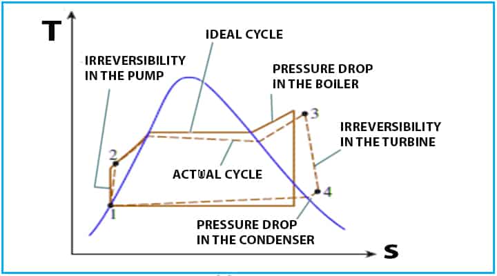
- So, obviously, the actual Rankine cycle will be different from the ideal ones.
- The losses are accounted and the entropy is varied.
Rankine Cycle with P-v Diagram
Let’s see the P-v diagram,
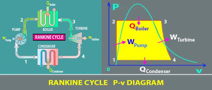
The irreversibility’s due to the fluid friction, heat loss to the surroundings the Rankine cycle differs from the ideal one. Losses like fluid friction drop the pressure in the boiler, condenser, and the piping between the components, and hence the network output is reduced. Thus, more heat addition will be required for maintaining the network output and hence more fuel or charge.
Rankine Cycle Equations or Formula & Thermal Efficiency
The general thermal efficiency equation of the simple Rankine cycle,
Thermal efficiency, η = WTurbine – WPump / QBoiler
Where,
- WTurbine is the work output
- WPump is work input
- QBoiler is the heat supplied.
Let’s consider the followings,
- h1: Enthalpy at point 1
- h2: Enthalpy at point 2
- h3: Enthalpy at point 3
- h4: Enthalpy at point 4
- WPump: Work done on the pump
- QBoiler: Heat input to the system
- WTurbine: Work done by the turbine
- QCondenser: Heat out from the system
- m: Mass flow rate
- ηefficiency: Efficiency of Turbine
- ηpump: Efficiency of Pump
Then we can write,
- QBoiler/m = h3-h2
- QCondenser/m = h4-h1
- WPump/m = h2-h1
- WTurbine/m = h3-h4
Thermal efficiency of Rankine Cycle, η
- η = WTurbine – WPump / QBoiler
- η = [ m(h3-h4) – m (h2-h1)] / [m (h3-h2)]
- η = [ (h3-h4) – (h2-h1)] / [(h3-h2)]
- η = (h3-h4 – h2+h1)/ (h3-h2)
- η = (h3-h2 – h4+h1)/ (h3-h2)
- η = [(h3-h2) – (h4-h1)]/ (h3-h2)
- η = 1 – (h4-h1)/ (h3-h2)
- η = 1 – (h1-h4)/ (h2-h3)
Actual Rankine Cycle: How Does it Looks?
The ideal Rankine cycle has no losses and it’s considered as an ideal power plant cycle. But in actual obviously there are losses and reduced work output.
- The compression and expansion by pump and turbine are not isentropic.
- Basically, these processes are non-reversible and the entropy is increased during these two processes it does not remain constant.
- So, it will increase the power required by the pump and reduced the power generated by the turbine mostly due to water droplets formation.
As the water droplets will condense water droplets will heat the turbine at a very high speed and the turbine will get eroded, the blades and efficiency of the turbine will be reduced. The solutions like superheating of steam are employed to overcome these problems. So, to overcome the losses and get more net power output some variations are adopted in the Rankine cycle. Some variations are discussed below, like
- Rankine cycle with reheat
- Rankine cycle with regeneration
Rankine Cycle with Reheat
The reheating cycle work is to remove the moisture carried by the steam at the final stages of the expansion process.
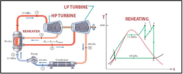
- In case of the reheat cycle, the two turbines work in the series arrangement.
- The first turbines accept the vapor coming from the boiler at high pressure.
- After vapor is passed through the first turbine it renters the boiler and reheated before passing to the second turbine which is a low-pressure turbine.
The reheating prevents the vapor from condensing during the expansion, thus reducing the damage to the turbine blades and improves the efficiency of the cycle because there will be more heat flow into the cycle at higher temperatures.
Rankine cycle with Regeneration
Regenerative is named because the fluid emerging from the condenser usually a subcooled liquid, is heating by the steam tapped from the hot portion of the cycle.
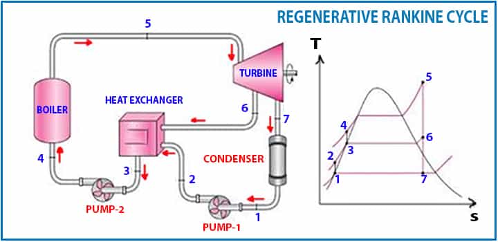
As you can see in the image above.
- The fluid at the Point 2 is mixed with the fluid at 4, so it will end up with saturated liquid at the Point 7 position.
- This is also known as direct contact heating.
- The regenerative cycle is commonly used in power stations.
Rankine Cycle Examples
In the thermal power plant, the Rankine cycle is used to produce electricity. Here, water is pressurized by the pump, takes up the heat and produces vapor in the boiler, and later on, expands in the turbine to generate electricity.
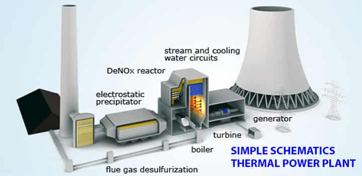
The details of the thermal power plant are already captured in a separate article.
FAQs on Rankine Cycle
What is Rankine cycle process?
The Rankine cycle is one of the most common cycles widely used by power plants. It helps to convert the pressure energy coming from the steam to mechanical energy with the help of steam turbines.
Four processes are:
1. Isentropic compression
2. Constant Pressure Heat Addition Process in Boiler
3. Isentropic Expansion Process
4. Constant Pressure Heat Rejection in Condenser
What are the four process of Rankine cycle?
The four processes of the Rankine Cycle are as follows:
1. Isentropic compression
2. Constant Pressure Heat Addition Process in Boiler
3. Isentropic Expansion Process
4. Constant Pressure Heat Rejection in Condenser
What are the main components of Rankine cycle?
There are four main components,
Pump (P)
Boiler (B)
Turbine (T)
Condenser (C)
Conclusion
Hence, we have learned the basics of the Rankine cycle along with T-S, P-V, diagrams, reheat, regeneration, etc. Any questions, please let us know. Our Videos on YouTube MechStudies – YouTube.