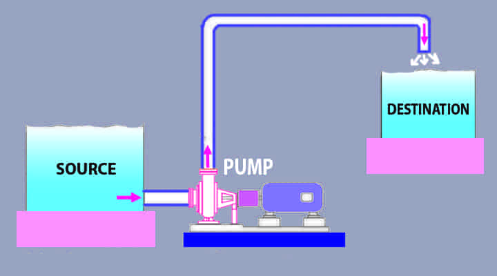
We will learn pump basics in this article. So, what is pump? Let us try to understand. When we are required to lift fluid from a lower elevation to a higher elevation, external equipment is required. This equipment is the pump. Around 18 – 20% of the world’s electrical power is consumed by pumps in many ways.
What is Pump & Basics?
Pump Basics
Let’s concentrate on the basics of the pump. Pumps are used to lift or transfer fluids from one place to another in almost all kinds of industries like domestic, industries, various plants, medical, commercials, agricultural, wastewater service, chemical & food processing, oil and gas sectors, etc.
Pump Definition
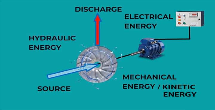
The pump has a driving component that is a motor (sometimes may be an engine), and a power source is connected to the motor.
- Once the pump is switched ON, electricity is supplied to the motor, and
- the pump does a mechanical action and changed the electrical energy into hydraulic energy, and
- lifts or transfers fluids from a lower elevation region to a higher elevation region.
Hence, A pump is defined as the mechanical equipment which lifts or transfers fluids from a lower elevation region to a higher elevation region by converting electrical energy into hydraulic energy.
- Pumps are of various types.
- These are operating based on various design principles.
- Working philosophy are different for different pumps.
- It needs a driver to operate.
- Driver may be motor or engine or gas or turbine etc. driven.
Function of Pump
The main function of pumps are as follows,
- Pump lifts liquids from lower elevation to higher elevation.
- It helps to circulation liquids from one point to another point.
- It increases the pressure or the head of pump to meet the required discharge pressure requirements.
- If a system loss the pressure, pumps are used to increase the pressure of the system to make it stable.
- Pumps are used to transfer required liquid flow rate.
Pump Basics Terms
To understand the pump or it’s working principle, there are few pump basics terms are required to know. These are.
- Volumetric flow rate
- Shut-off head
- Suction Head
- Static suction head (hs)
- Suction lift
- Static discharge head (hd)
- Friction head
- Total Head
- Vapor pressure
- Net Positive Suction Head
- Specific speed
- Theoritical pumping power
- Actual pumping power
01. Pump Volumetric Flow Rate: Volume flow rate means the capacity of the liquid per unit time which is transfer through the pumps. It is the rate of water flow. Pump capacity is expressed in volumetric flow rate and head. It is measure in m3/s or ft3/s.
The volume of flow, ‘V’ and time is ‘t’, then the volume flow rate, q = V/t. If the mass flow rate is ‘m’, and density is ‘ρ’, and the volume flow rate, then, we can write,
- m = ρ x q,
- or, q = m/ρ
Hence, it can be defined as the ratio of mass flow rate to density. In S.I. units, the volumetric flow rate is measured in m3/s, and F.P.S unit, it is measured in ft3/min.
02. Pump Shut-off head: The shut-off head is one of the most important parameters in the pump. It is defined as the head with respect to zero volumetric flow rate.
03. Pump Static head: Static head means the height difference between the elevation of the source of liquid and the elevation of the discharge liquid.
- Suction static head is totally depending on the elevation.
- It doesn’t depend on the flow rate.
- It depends on the specific gravity of the liquid, at a given pressure.
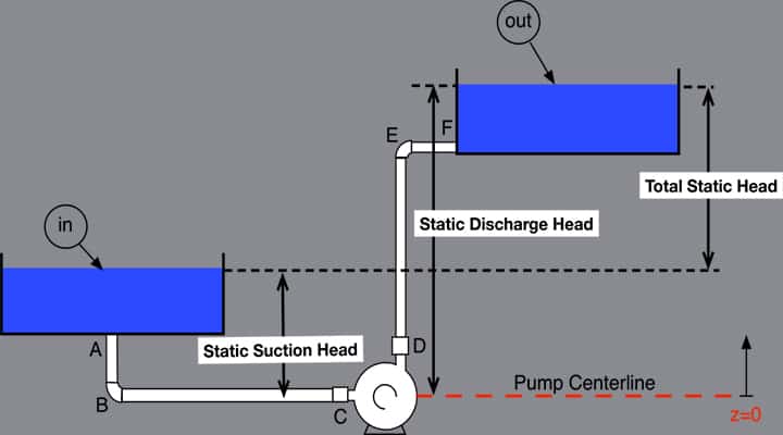
04. Pump Static Suction Head: The static suction head is a part of the static head. It is used when liquid source is above the pump center line. It describes the height from the liquid source to the pump center.
- Normally it is denoted by ‘hs’.
- This value is considered as +ve.
- Doesn’t depend on the liquid flow rate.
- Depends on the specific gravity, at a given pressure.
05. Suction Lift: This term is used when pump is placed above the liquid surface, elevation wise. This is the vertical distance between the liquid surface and the pump center line, when pump is placed above.
- This height is limited to 10m, due to the limitation of atmosphere.
- This value is considered as, -ve, as it is always opposite direction to static suction head.
06. Static Discharge Head: The static discharge head is also a part of the static head. It is used to specify the distance between the elevation of the liquid in the destination and the pump center line.
- Normally it is denoted by ‘hd’.
- Doesn’t depend on the liquid flow rate.
- Depends on the specific gravity, at a given pressure.
07. Friction head: The pump has a piping system and all pipes will have many fittings, bends, straight lengths based on the system design. Hence, these all provide the resistance to the flow which is required to overcome so flow will be continuous in the system. This head is known as friction head & it is the loss that needs to be overcome. The friction head depends on the following,
- Size of the pipe
- Pipe condition
- Age of pipe
- Type of pipe
- Nos of fitting
- Nos. of bends
- Pipe length
- Total system configuration
- Liquid flow rate
- Type of liquid
08. Total Head: The total head in a system is defined as the total pressure difference between the inlet and outlet of the pump.
- In case of source is above the pump, difference between the discharge head and the suction head plus the friction head.
- In case of source is below, it is the sum of discharge head, suction lift, and friction loss.
- TDH = Static Height + Static Lift + Friction Loss
09. Vapor Pressure: At a given temperature, vapor pressure is the pressure that is exerted by the gas in equilibrium with either a solid or liquid in a closed container. It is the pressure, in which molecules enter the vapor state at a specified temperature. If you boil a liquid, you can observe it.
- It is simply an indication of the evaporation rate of the liquid.
- If the temperature increases, vapor pressure will also increase.
Various units are used for vapor pressure:
- Pascals (Pa),
- bar (bar),
- tor (mm Hg),
- atmospheres (atm),
10. Net Positive Suction Head: The Net Positive Suction Head – NPSH – is defined as the difference between the Suction Head, and the Liquids Vapor Head and can be expressed as: NPSH = hs – hv, Where,
- Hs – Suction head
- Hv – Liquid vapor head
There are two terms which are very important,
- NPSHr
- NPSHa
NPSHr: NPSHr means NPSH required for the pump selection. It is one of the main functions of the selection of pumps so that the pump will not have any cavitation problems during operation.
- It is the lowest value of NPSH in which pump will run without any cavitation.
- It is normally provided by manufacturer.
- Best wat way to determine it by actual testing.
- NPSH-R is the value at which the discharge pressure is reduced by 3% because of the onset of cavitation.
NPSHa: NPSHa means NPSH available. It is calculated from the suction side of the pump. It is basically a function of the system based on which a pump operates. There are two options.
Option-1: NPSHa when the pump is below the source, NPSHa = Pa + hs – pv – pf, Where,
- Pa – Absolute pressure head on the liquid surface
- Hs – static head above pumps center line
- pv – absolute liquid vapor pressure head at pumping temperature
- pf – the suction friction head losses.
Option-2: NPSHa when the pump is above the source, NPSHa = Pa – hs – pv- pf
NPSH-A is always more than NPSH-R for any operating conditions to avoid cavitation of pumps. Look at the few pumps used in our daily life:
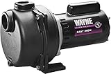

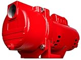
- Outdoor Care - This 2 HP WAYNE model WLS200 outdoor lawn sprinkling pump is perfect to keep your garden and lawn green all season long, as well as move water to your sprinkler system.
- Tough And Durable - Heavy-duty cast iron volute that provides a long life for your water pump applications.
- Efficient Design - 2” NPT suction with 1-1/2” NPT discharge for maximum water flow.
- Usage - Use the WLS200 to sprinkle lawns and gardens, and empty stock tanks. Designed to operate underground sprinkling systems, draw water from wells, lakes or ponds for watering, pool filling or any applications where high-water volume is needed.
- Quality You Deserve - Proudly assembled in the USA for quality you can trust. Warrantied for 1 year for dependable, efficient performance.
- BUILT TO LAST: Rugged cast iron pump housing and glass-filled thermoplastic impeller for well water and lake water
- MOTOR SPECIFICATIONS: 230 VOLTS, 10.9 running Amps, Capacitor-run PSC design, 7332 locked rotor watts, thermally protected, CSA listed in the US and Canada
- ONE-TIME PRIMING: No additional priming is required after initial fill; follow the priming instructions in the owner's manual
- UP TO 76 GPM at 10 PSI: 64 GPM at 30 PSI - can handle up to 21 sprinkler heads with 1/2-inch fittings or 10 sprinkler heads with 3/4-inch fittings in each zone
- SPECIFICATIONS: 2.0 HP, 230 Volts, 2-inch Female NPT threaded intake; 1.5-inch Female NPT threaded discharge, Max pressure 49 PSI
10. Pump Specific speed: Specific speed or pump specific speed is defined as the parameter to specify the size or shape of the pump impeller. It is a dimensionless parameter. Specific speed means, the following,
- It helps to select appropriate impeller size.
- It depends on shaft speed.
- It also depends on the flow rate and differential head at BEP.
- It is essential when comparison between two pumps are required.
- It doesn’t depend on pump size.
The friction head depends on the following,
- Shaft speed
- Flow rate
- Differential head etc.
Specific Speed is written mathematically, as follows, Ns = n q1/2 / h3/4 , Where
- Ns = specific speed
- n = pump shaft rotational speed (rpm)
- q = flow rate (m3/h, l/s, l/min, m3/min, GPM (US & British) at Best Efficiency Point (BEP)
- h = head rise (m, ft)
Specific speed is used to:
- Hydraulic design
- Pump performance
- Impeller size, as well as trimming
11. Theoretical Pumping Power: Theoretical Pump power calculation (P). Here, P = ρ x g x q x h, Where,
- P = Power, in Watt
- ρ = Density of fluid, kg/m3
- g = Gravitational acceleration, m/s2
- q = Flow rate, m3/s
- h = Head, m
12. Actual Pumping Power: Actual Pump power calculation, P’
Here, P’ = Theoretical pumping power / pump efficiency
P’ = ρ x g x q x h / η [Where, η = efficiency of pump]
Would you like to understand ‘what is pump’ with animated video, then look out our YouTube video below and subsequently we will learn the types of pumps, as well
What are the Different Types of Pumps Used in Industries?
Let’s see a glance at different types of pumps! Pumps are classified into two main groups, and it is further classified into many groups.
- Positive Displacement Pump
- Dynamic Pump
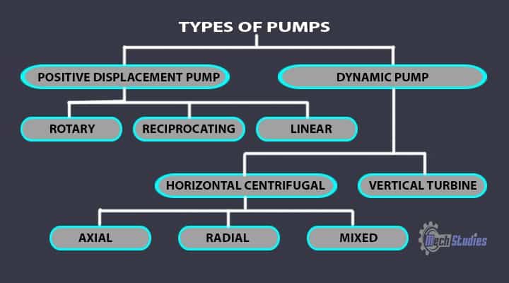
01. Positive Displacement Pump Types
Positive-displacement pumps are classified into three types,
- Rotary-type
- Reciprocating-type
- Linear-type
Rotary Type Pumps: The classification of these types of pumps depends on the types of rotating elements and they include:
- Gear pumps
- Lobar pumps
- Screw pumps
- Labyrinth pumps
- Vane pumps
- Radial-plunger pumps
- Vibratory pumps.
Reciprocating Pump Types: The classification of these types of pumps depends on the types of rotating elements and they include:
- Plunger pumps
- Diaphragm pumps
- Piston pumps
- Radial piston pumps
Linear Pumps Types: These pumps are different kinds, like,
- Rope pumps
- Chain pumps
02. Dynamic Pump Types
Dynamic Pumps are classified into two types:
- Horizontal Centrifugal Pumps
- Turbine Pumps
Horizontal Centrifugal Pumps Types: Horizontal Centrifugal Pumps are classified into three types:
- Axial flow pump
- Radial flow pump
- Mixed flow pump
Turbine Pumps Types: Turbine Pumps are classified into three types:
- Vertical pump
- Submersible pump
After getting the pump classifications, let us see the basic details of each type of pump.
Description of Pump Types
I. Positive Displacement Pumps
What Does Positive Displacement Pump Mean? As the name suggests, a positive displacement pump means associated with the displacement of fluids. This pump transfers fluid by trapping a fixed amount of fluid and displaced it into the discharge section. The positive displacement pump can be different kinds of arrangement with different types of parts. This pump can have,
- pistons or
- plungers or
- diaphragm, or
- gears, or
- lobes, etc.,
Based on the above different parts, positive displacement pumps are classified into many types. It takes some amount of fluid from one end, that is the suction side and positively displaced in the discharge side.
- It is generally used for pumping oil wells and viscous liquids applications.
- In this pump, volume at each cycle of operation is constant.
- A positive-displacement pump does not have shutoff head.
- Safety of relief valve is necessary at the discharge side for safety purpose.
- This pump cannot operate at discharge valve closed condition. In case it operates, discharge pipe or the pump will be damaged.
| Positive Displacement Pump Advantages | Disadvantages of positive displacement pumps |
| Widely used for dosing and injection pumps | Many parts associated with wearing. |
| High-pressure application | A pressure relief system is a must from the safety point of view. |
| Suitable for high viscous fluids | It can produce noise. |
| Very good suction capacity, even with gas content | Suitability is reduced for high-speed operation. |
| Suitable for high viscosity | |
| This pump has the provision to adjust the stroke to adjust the flow rate. | |
| It is suitable for low-flow applications as well. | |
| It is suitable for low drive speeds. |
Let’s try to understand the basics of each type of positive-displacement pumps,
- Rotary-type
- Reciprocating-type
- Linear-type
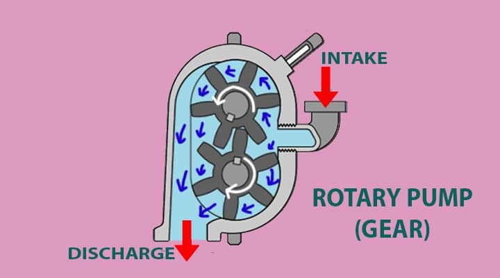
01. Rotary Pumps
The rotary pump transfers fluids by using a rotating mechanism. It creates low pressure or vacuum and takes up the fluids from the source. After taking up, due to the rotation, fluid is transferred.
- These pumps have rotating parts and stationary parts and the clearance between these parts is very small.
- Small clearance helps to minimize the leakage to the suction side from the discharge side.
- These are normally used for high viscosity liquids.
- Designed considering lower speeds.
| Advantages of Rotary Pumps | Disadvantages of Rotary Pumps |
| Very efficient for viscous fluids. | Due to low clearances between the stationary and rotating parts, speed is low. |
| No separate priming is required. | High speed may cause erosion and reduce the efficiency. |
| It can handle more fluid, than the reciprocating pump at same weight. |
The classification of these types of pumps depends on the types of rotating elements and they include:
- Gear pumps
- Lobe pumps
- Screw pumps
- Vane pumps
- Rotary plunger pumps
- Progressive cavity pumps
Let’s learn all types of pump basics for clearing the concept.
0A. Gear Pump Basics
Let’s try to understand the basics of a gear pump. In this type of pump, mechanical energy is converted into hydraulic energy with the help of gear arrangement. It has one drive gear and one gear is driven. The gear can be internal gear or external gear arrangements.

| Advantages of Gear Pumps | Advantages of Gear Pumps |
| Simple design | Difficulty in handling Solid and sludge type material |
| Compact & less space requirements. | No flexibility in end clearance |
| High pressure generation | Any small displacement in gears, large noise may be generated. |
| Low noise | Small displacement will incur a reduction of pump efficiency |
| Suitable for bidirectional flow | |
| Low pulsation flow |
Applications of Gear Pump
- Chemical transportation & handling
- Adhesive handling
- Petrochemical industry
- Food industry
- Hydraulic power units
- Plastic processors
- Polymer processors
0B. Lobe Pump Basics
Let’s try to understand the basics of a lobe pump. In the lobe type of pump, mechanical energy is converted into hydraulic energy with the help of lobe arrangement. It is similar to a gear pump, however; it uses lobe instead of gears.

Also, there is some clearance between lobes. One lobe is connected to the driver and other one is driven.
| Advantages of Lobe Pumps | Disadvantages of Lobe Pumps |
| Simple design & compact | Timing gears are essentials to control the lobes |
| Easy to handle slurries, paste, foods, solids, etc. | Problem with low viscosity liquids |
| No wear & tear, as both the lobes are not touched. | |
| Low pulsation flow | |
| Low noise |
Applications of Lobe Pump
- Polymer & paint industries
- Paper industries
- Soap industries
- Food industries
- Rubber plant
- Medical application
Let’s see the difference between gear pumps & lobe pumps.
| Description | Gear Pumps | Lobe Pumps |
| Action | In this pump, gears are used for creating a pumping action. | In this pump, lobes are used for creating a pumping action. |
| Clearance | No clearance between gears | Slight clearance between two lobes |
| Loss | It has wear & tear | No wear & tear |
| Limitation | Not suitable for solid particles as no clearance between gears | Suitable for solid particles as there is some clearance between lobes |
| Application | Chemical, adhesive handling, etc. | Widely used in food industries |
0C. Screw Pump Basics
The screw pump is one type of positive displacement pump which consists screws or rotors. These screws are rotating and forming a cavity to increase the pressure and transfer liquid from one place to another.

The screw pumps can be as follows:
- Single screw
- Twin screw
- Three screw
- Four screw
- Five screw etc.
| Advantages of Screw Pumps | Disadvantages of Screw Pumps |
| Robust construction | Expensive |
| Low vibration | Difficult to maintain |
| It can be operated at high speed | Speed cannot be lowered below 50 |
| No contamination | |
| Less wear & tear | |
| High efficient | |
| Low operation & maintenance |
Application of Screw Pumps
- Handling Lubricants
- Handling vicious liquids
- Fuel injections
- Multiphase pumping
- Heavy oil pipeline
0D: Vane Pump Basics
The is one more positive displacement type of pump used in many industries. This is a vane pump. In this type of pump, pressure is increased with the help of vanes. Here, vanes are attached to the rotors.

Vanes can be able to adjust in length and pressure will be changed accordingly.
| Advantages of Vane Pump | Disadvantages of Vane Pump |
| Suitable for making vacuum. | Design is complex. |
| Suitable for low viscosity fluids at high pressures. | Not suitable for high viscous fluids at high pressure. |
| No issue with dry runs for shorter period of time. |
Applications of Vane Pumps
- Automobile industries
- Automatic transmission pumps
- Power steering etc.
02. Reciprocating Pumps
Reciprocating pumps have piston and cylinder arrangement and due to the reciprocating motion of the piston in the cylinder, the pump works. The cylinder has a suction and discharges side with valves. Piston moves and creates low pressure to draw the fluid. After suction, the piston pushes back and creates pressure on the fluid and fluid discharge with high pressure.
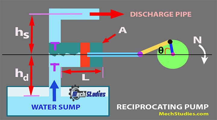
- It is widely used in high pressure and low flow applications.
- Works based on reciprocating action.
| Advantages of Reciprocating Pump | Disadvantages of Reciprocating Pump |
| It can produce high head. | High maintenance. |
| No priming required. | Low flow. |
| It provides high suction lift. | Difficult for high viscous fluids. |
| Air can be used. |
The classification of these types of pumps depends on the types of rotating elements and they include:
- Plunger pumps
- Diaphragm pumps
- Piston pumps
- Radial piston pumps
03. Linear Pumps
In this type of pump, as the name suggests, the displacement of the fluid happens linearly.
- In a linear pump, no calibration is required.
- Due to the linear motion of the piston, it creates noise.
- It is installed at a faraway distance from people.
These pumps are different kinds, like,
- Rope pumps
- Chain pumps
II. Dynamic Pumps
Centrifugal force is the main driving force in dynamic pumps. Due to this force, the pump develops velocity in the liquid. This velocity is converted into pressure.
- It has impeller which creates low pressure in order to draw fluid.
- Widely used for low viscosity fluids.
- High flow rate, low pressure applications.
- Low maintenance
Dynamic Pumps are classified into two types:
- Horizontal Centrifugal Pumps
- Vertical Turbine Pumps
0A. Centrifugal Pumps
Centrifugal pumps are used to transfer liquid by converting mechanical energy into hydraulic energy.
This pump creates a centrifugal force by the rotation of the impeller.
- It transfers transfer liquid from one place to another place.
- The main force is centrifugal force
- Kinetic energy changed into a pressure head.
- Pumps are driven by motor or engine, as applicable.
Let’s try to understand all types of horizontal centrifugal pumps as below:
- Axial flow pump
- Radial flow pump
- Mixed flow pump
01. Axial Flow Pump
Axial flow pump is a type of centrifugal pump. The axial flow pump is also called a propeller pump. As the name suggests, in this pump fluid moves axially through the pump impeller. In this kind of pump, the casing splits axially.

The impeller is mounted in a pipe and operated by motors or engines. This pump provides high liquid flow with a low head.
| Advantages of Axial Flow Pump | Disadvantages of Axial Flow Pump |
| Suitable for high flow rate | Problem in suction lift |
| Suitable for high flow with low head and vice versa | |
| Efficient for high flow with low head and low flow high head application. |
Application of Axial Flow Pump
- Sewage application
- Irrigation application
- Drainage application
02. Radial Flow Pump
Radial flow pump is one type of centrifugal pump and it is widely used in most of industries. This pump is called radial flow pump, as its discharge is radial with respect to the impeller. The discharge & the shat makes 90 deg. In the case of the Radial split pump, the casing splits radially.

The impeller rotates and with the help of centrifugal force, the pump transfers liquid from one place to another. Normally, this pump is used when low flow and high head requires.
| Advantages of Radial Flow Pump | Disadvantages of Radial Flow Pump |
| Simple & compact design | Not suitable for high viscous liquids |
| It can handle incompressible fluid as well | Not suitable for high solid contents |
| It can easily handle low viscous liquids, however, it can also handle liquid with gas or slightly solids as well. | |
| Efficient | |
| No axial thrust and no balancing problem | |
| Low bearing loads due to open impeller construction. | |
| Long life |
Application of Radial Flow Pump
- Water industries
- Waste water & waste water treatment
- Food industry
- Beverage industry
- HVAC system
- Chemical industries
- Ship building
- Power plants
03. Mixed Flow Pump
The mixed flow pump is another type of centrifugal pump. Based on the name, we can easily understand that this flow is a mixture of axial & radial flow. That means, mixed flow consists of both types of flow, that is axial & radial.
In this type of pump, the impeller is designed in such a way that both types of flow can be incurred. In this pump, if the impeller has a low specific speed, then it needs to be placed in a volute casing. In case, if the impeller has a high specific speed, then it needs to be placed in a combination of tubular casing & one diffuser.
The impeller is placed within a pipe which is similar to an axial flow pump. But here, an additional turning mechanism is provided to use the centrifugal force which implies a radial flow pump. Hence, both types of flows are working & create high flow. Combines radial and axial flow, producing a conical flow pattern around the impeller shaft.
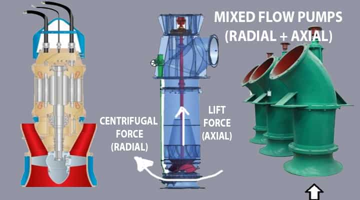
Pressure energy created in the mixed flow pump, as follows:
- One portion by centrifugal force which is due to impeller radial action
- Other portion by lifting the impeller blades on the fluid due to impeller axial action
| Advantages of Mixed Flow Pump | Disadvantages of Mixed Flow Pump |
| Suitable for very high flow rate. | Not suitable for high head application |
| It can develop medium head as well due to its partial centrifugal action. | Not suitable for low head application as well. |
| Not simple design like axial flow pump |
Application of Mixed Flow Pump
- Irrigation
- Water industries
- Thermal power plants.
What are the Differences between Axial Flow, Radial Flow & Mixed Flow Pump?
There are many differences between Axial Flow, Radial Flow & Mixed Flow Pump. Let’s tabulate to understand it clearly,
| Axial Flow Pump | Radial Flow Pump | Mixed Flow Pump |
| Pump flow is axial to the pump axis | Pump flow is radial to the impeller | Pump flow is mixed and it consists of axial & radial |
| Discharge flow is axial to the pump axis | Discharge flow is perpendicular to the pump axis | One part is axial and another part is radial |
| It has propeller action | No propeller action | It has partial propeller action |
| No centrifugal force action | It has centrifugal force action | It has partial centrifugal force action |
| In this type of pump, it split axially | In this type of pump, it split radially | |
| This pump is used for high flow but low head | This pump is used for high flow but high head | This pump is used for high flow but medium head |
| Irrigation, drainage, etc. | Wastewater, HVAC, food industries, etc. | Irrigation, thermal power plants, etc. |
Vertical Turbine Pumps
As the name suggests, these kinds of pumps are vertical. Vertical turbines are widely used for pumping in the following industries,
- Irrigation system,
- Power plants,
- Steel plants, etc.
Parts of a Pump: What are the Basic Components of Pump?
There are basics parts of the pump, based on the types of pumps. We have already learned parts of reciprocating pumps, like:
- Suction Pipe
- Suction Valve
- Delivery Pipe
- Delivery Valve
- Cylinder
- Piston and Piston Rod
- Crank and Connecting Rod
- Strainer
- Air Vessel
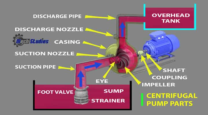
In the same way, parts of the pump for Centrifugal Pumps, are as follows:
- Casing
- Impeller
- Suction pipe with a foot valve
- Strainer and
- Delivery pipe etc.
Parts of pumps are illustrated for centrifugal pumps and reciprocating pumps, as these are the widely used pumps in various industries.
How Does a Pump Work?
There are so many types of pumps and the working principle of each pump is different. However, the basic principle is the same and here, we are going to explain how does a pump work in general. Let’s get into the step-by-step explanation!
- Step#1 Start of Driver: The pump is connected to a motor or engine or any other driver and the driver is required to start to operate.
- Step#2 Intake of Fluid: We have already learned that pumps transfer fluid from one place to another. Hence, it is necessary to get the fluid into the pump. In case of reciprocating pumps, a negative pressure is created in the cylinder due to the movement of the piston. However, pump priming is required for the centrifugal pump, as the impeller cannot create much pressure difference in the pump.
- Step#3 Limitation of Negative Pressure: Pressure should not be below the vapor pressure, else, bubbles will be formed and cavitation can occur which will damage the pump.
- Step#4 Increase in Pressure Energy: In a centrifugal pump, volute and diffuser help to increase the pressure of the fluid. Centrifugal force is created due to the rotation of the impeller and this force is acted on the fluid too. Water is transferred through the volute (gradually increased cross-section) and velocity is reduced which is further converted into pressure.
In case of a reciprocating pump, the piston is connected to the crank through the connecting rod, and the crank is connected to a driver. After sucking the fluid, the piston moves opposite, and pressure is generated on the fluid. Hence, we have got the basics of the pump working philosophy.
Troubleshooting for Pump & Pumping System
What are the reasons for Low Discharge Pressure?
There may be a wide reason for low discharge pressure, although the pump is designed for high pressure. Let’s see what are the main reasons for low discharge pressure.
- Condition of Suction System: The pump takes the liquid through a suction strainer. The suction strainer filtrates the liquid so that unwanted particles are not able to pass through the pump. If the suction strainer is not clean properly, the flow rate will be reduced which contributes to a reduction of discharge pressure.
- Suction valve: Check if the suction valve is slightly closed during start-up. It should be fully open.
- Size of the orifice or nozzle: Check if the orifice size or nozzle size is matching with designed size. A change in nozzle size will result in a change in discharge pressure. If nozzle size, is high with respect to the design size, then the flow rate may increase but there will be a reduction of pressure.
- Pump speed: Pump impeller speed shall be in line with the designed speed. The reduction in pump speed may result in a reduction in pump discharge pressure. The pump impeller, as well as the pump shaft, is coupled with the motor shaft. Coupling should be checked and also motor wiring, winding, bearing, etc. shall be checked properly. Also, check the belt condition, tightening of belts, etc.
- Pump priming: The pump should have proper priming in case of centrifugal pump or non-self-priming pumps. If priming is not done completely, its efficiency, as well as discharge pressure, will be reduced.
- Materials of pump: Pump material shall be properly selected based on the applications. The same needs to be checked if all are as per the design and conditions of each part. Any wrong material selection or any problem in any parts shall be taken into considerations.
Advantages of Pumps
These are many advantages of Pump, as follows:
- Pumps are very useful equipment to transfer fluids.
- It is available from a very small capacity to a very large capacity.
- It is widely used as circulating equipment in many systems like chilled water circuits, cooling tower circuits, and many more.
- Noise is less comparative with other rotating devices.
- Pumps can be used (reciprocating pump) for gaseous applications as well.
- No leakage, fewer losses.
- A wide range of constructions, a wide variety of materials is used for pumps.
Disadvantages of Pump
These may be some disadvantages as well of Pump:
- Operation of pumps is smooth, however, it may be encountered cavitation. It hurts the pump.
- The pump can have corrosion problems.
- Many times, handling fluids may have problems. For example, reciprocating pumps are not suitable for viscous fluids.
- Centrifugal pumps cannot work without priming.
- There is a limitation of piston or impeller speed.
Applications of Pump
The application of pump is wide, a few of them are listed below:
- Water storage & transfer.
- Domestic application.
- Sewage & slurries application.
- Fire fighting & protection system
- Manufacturing, chemical, oil & gas, pharmaceutical, food, aviation, HVAC, etc. industries.
- Aquarium, water fountain, and pond filtering, etc.
- Even in the automobile sector, pumps are used.
- In thermal power plants, or nuclear power plants, or hydroelectric power plants, pumps are one of the vital equipment.
Conclusion
Hence, we have got an idea about the pump basics along with an understanding of what is pump, its parts, working principle, etc. Any questions, please write to us. Refer Our YouTube for Animated Videos

You need to take part in a contest for among the finest blogs on the web. I will suggest this website!
You are my breathing in, I own few blogs and very sporadically run out from to post : (.
I like that you pointed out how pumps could lift liquids from a lower elevation to a higher elevation. I was skimming through a technical book earlier and it showed how pumps work. From what I’ve read, it seems there are various types of pump systems now too, like mine fire pump systems.