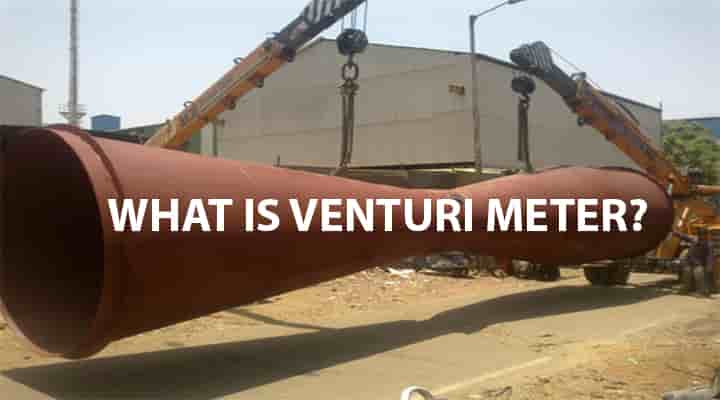
Venturi Meter or Venturimeter or Venturi Tube, a well-known device in fluid mechanics that uses venturi effects. Measuring the rate of flow of liquid is essential many times and this simple device is widely used to do it precisely. The Venturi meter or Venturi tube is a flow measurement device and it works based on Bernoulli’s equation. How does venturimeter work? What is Venturi effects? Let’s explore the whole concept! [Note: A video is included for visuals at the end.]
What is Venturi Meter or Venturi Tube? Venturi Effects
Definition of Venturi Meter or Venturi Tube
Venturi Meter or Venturi Tube is a mechanical device used to measure the flow rate by converting pressure energy into kinetic energy. Venturi meter or venturi tube means,
- The device measures the velocity or flow rate or discharge of fluid in the pipe.
- It works based on Bernoulli’s equation & continuity equation.
- Each venturi meter has a cylindrical entrance section, one converging part, a cylindrical throat, and a diverging part.
Venturi Effects
The main principle by which the venturi meter works is called venturi effects. It can be defined as the effects or principle by which the velocity of a fluid increases and pressure decreases when it flows through a constricted area.
History of Venturimeter
Do you know who has invented the venturi meter? Let’s see it’s in history! The main concept of the venturi meter has come from G.B. Venturi and it was further developed with the help of An American Engineer Clemans Herchel. The name venturi meter came from G.B Venturi.
Why Does Flow Measurement Essential?
The measurement of flow is very much essentials now a day. In all industrial applications, flow measurements can be explained as follows:
- System control: To control the system, flow control is mandatory. Suppose water is flowing in a chilled water circuit and suddenly flow reduces. What will happen then? The system will be inefficient or may stop. But if there is a flow measuring device that gives the data, this problem will be easily solved.
- Energy-saving & Cost Saving: Flowmeter pointed out when the process is running efficiently or inefficiently. It helps to control the proper flow as well as increase efficiency. Hence, it helps us to save energy as well as cost.
- Application: The flowmeter application is in various fields. It helps to measure from liquids to gases, like water, steam, carbon-di-oxide, compressed air. The flow rate is measured by the followings: Orifice, Flow nozzle, and Venturi meter or venturi tube
In this chapter, we will explore Venturi Meter!
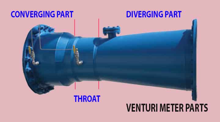
Parts of Venturi Meter or Venturi Tube
To create the venturi effects, a Venturi Meter or Venturi Tube is consisted of the following parts:
- Entrance section (Optional, depends of manufacturer’s design)
- Converging part or converging cone
- Throat Part
- Diverging Part or diverging cone
- Flanges
- Inlet & Outlet Pipe (Connection, not part of venturimeter)
Let’s consider a pipe that is connected to a venturi meter. In the pipe fluid is flowing so first it enters into a converging cone then Throat and then Diverging Cone.
Entrance Section
This is the section having the size of a pipe to which it is attached.
- Normally, it is not considered as a part of venturi tube but few manufacturer extended a connection to it.
- It should be proceeded by a straight pipe and the length should not be less than 5 to 10 times the pipe diameter, in case there is one short section within venturi meter.
- It should be free from fittings, misalignment, and other sources which creates large-scale turbulence.
Converging Part
This converging part is the starting part of the venturi meter and it is attached to the entrance. Converging means gradually decreasing. Hence, the converging part means the area which is gradually decreased.
It is starting section of the venturi meter which is attached to the inlet pipe. When the water flows through the converging part, it signifies the water flows through the gradually decreased area.
- Now, as the area decreased – the velocity of the water will be increased as per contuinity equation. We know, a1 v1 = constant. If a1 ↓ then v1 ↑
- If velocity is increased – pressure energy will be decreased as per Bernoulli’s equation. We know, Pressure head + Velocity head + Potential head = constant. If velocity head ↑ then pressure head ↓
- The other end of converging is attached to the throat.
- The converging takes place normally at 21±2° angle.
Throat Part
The throat is placed in the middle of the venturi meter or venturi tube. This is a small cylindrical piece that connects the converging part and diverging part.
- One side of the throat is connected to the converging part and the other side is connected to diverging part.
- Normally throat diameter is ¼ to ¾ of the inlet pipe diameter.
- The length of the throat part equals to its diameter.
- When water flowing through this throat area, the cross-sectional area remains constant
- The area is constant means the velocity of flowing water as well as pressure energy remains constant.


- 1. Made of quality engineering POM plastic, good workmanship, sturdy and durable.
- 2. With outstanding chemical resistance to most chemical. Efficient and compact differential pressure injector device.
- 3. Economic and lower cost choice for you.
- 4. Suitable for 1/2 inch, 3/4 inch or 1 inch BSP inlet/outlet connector.
- 5. Applicable for agriculture irrigation system fertilizer and chemical injection.
Diverging Part
This diverging part is the last part of the venturi meter or venturi tube and it is attached to the delivery pipe. Diverging means the area will be increased. This part of the venturi meter is attached to the outlet pipe. When the water flows through the diverging part, naturally the area will be increased.
- Now, as the area increased – the velocity of the water will be decreased as per contuinity equation. We know, a1 v1 = constant. If a1 ↑ then v1 ↓
- If velocity is decreased – pressure energy will be increased as per Bernoulli’s equation. We know, Pressure head + Velocity head + Potential head = constant. If velocity head ↓ then pressure head ↑
- The angle of the diverging part is 5 to 15 degrees.
- The low diverging angle helps to avoid the flow separations as well as eddies formation
- Flow separation, eddies formation creates due to loss in energy
- Kinetic energy is recovered into pressure energy and loss of energy is less.
- The diffuser is angle about 5° to 7° and this low angle helps not to separate the flowing fluid from the boundary.
Flanges
Venturi meter is connected between pipes. So, it is necessary to connet it with that pipes by a connection. Normally flanges are provided to connect the pipe.
Inlet & Outlet Pipes
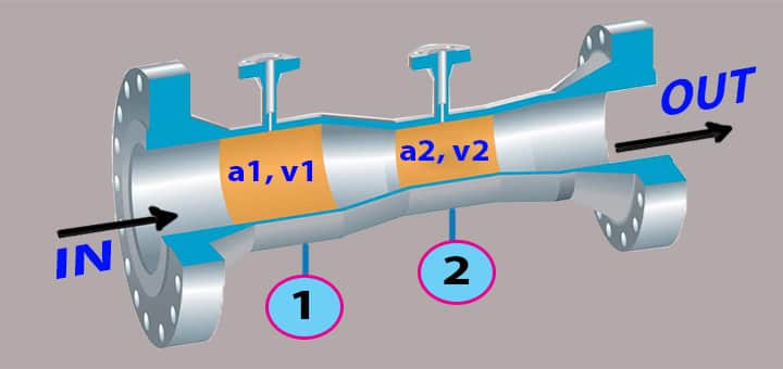
These are not the parts of venturi meter and but venturi meter is placed between them so that liquid can pass and flow can be measured. Look at the basic part of a common venturi meter or venturi tube.
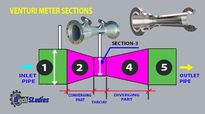
The name of parts and connections of a venturimeter or venturi tube is as follows,
Connections
- 1: Section 1 implies inlet.
- 5: Section 5 Outlet Pipe
Parts
- 2: Section 2 Converging Section,
- 3: Section 3 implies Throat,
- 4: Section 4 Diverging Section,
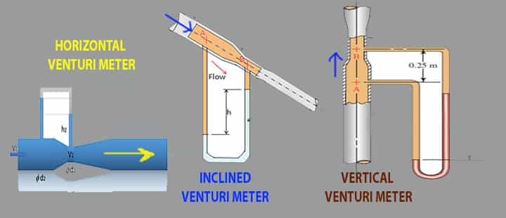
Type of Venturi Meter or Venturi Tube
Venturi meter or venturi tube is classified into three types,
- Horizontal venturi meter
- Inclined venturi meter
- Vertical venturi meter
Horizontal Venturimeter or Venturi Tube
- Horizontal means the mounting of this type is horizontal.
- Widely used flow meters.
- In case of, horizontal pipe, it is used.
- Kinetic energy is high, as it flows horizontally.
- Potential energy is low as its weight in the particular control volume is less.
Vertical Venturimeter or Venturi Tube
- Vertical means the mounting of this type is vertical.
- In case of verticle pipe, it is used.
- Due to its vertical movement, velocity is becoming less.
- Less velocity incurs lower kinetic energy (only if the flow is upward).
- Potential energy is very high as its weight in the particular control volume is high.
Inclined Venturimeter or Venturi Tube
- Inclined means the mounting of this type is inclined instead of horizontal or vertical.
- In case of an inclined pipe, it is used.
- Due to its inclined movement, velocity is within the horizontal and vertical types.
- Moderate velocity incurs moderate kinetic and potential energy.
Working of Venturi Meter or Tube & Venturi Effects
Assumptions of Venturi Meter & Venturi Effects
There are few assumptions for venturi effects,
- The inner side of the venturi meter is frictionless.
- The fluid is incompressible fluids
- The fluid flow is steady & irrational.
Bernoulli’s Equation & Continuity Equations
We have already learned Bernoulli’s Equation. So,
P.E + K.E + Pt.E = Constant.
Where,
- P.E = Pressure energy = p
- K.E = Kinetic Energy = 1/2 ρ v2
- Pt. E = Potential Energy = ρgh
- ρ = Density of fluid
- g = Gravitational acceleration
- v = Velocity of fluid
As per Bernoulli’s Equation,
- P.E + K.E + Pt.E = Constant
- p + 1/2 ρ v2 + ρgh = Constant
Now, dividing ρg – both sides,
- (p + 1/2 ρ v2 + ρgh)/ρg = Constant/ρg = Constant
- (p + 1/2 ρ v2 + ρgh)/ρg = Constant
Here, ρ & g both are constant for a particular fluid, hence, constant/ρg = constant.
So, we can write,

Which implies,
Pressure head (P.H)+ Kinetic head (K.H)+ Potential or Elevation Head (Pt.H) = Constant.
Where,
- P.H: Pressure head = p/ρg
- K.H: Kinetic head = v2/2g
- P.t.H: Potential head = h
- p: Pressure,
- ρ: Liquid density,
- g: Gravitational acceleration
- h: Height
- v: Water velocity
- z: Elevation
As per the continuity equation, for specific fluid flow,
Area (a) x Velocity (v) = constant.
Venturi Tube Principle Description
The principle behind the operation of the Venturi meter or venturi tube is the Bernoulli effect as well as the Continuity equation. In the venturi meter, the fluid flow rate is reduced due to the reduction of the cross-sectional area.
- Any point of flowing fluid in the venturi meter, there will be pressure energy, potential energy, and kinetic energy.
- Any two points of flowing fluid, some of these energies are the same.
- The total energy at any point in the wider diameter is equal to the total energy at any point in the narrow diameter.
Explanation Venturi Effects
We will explain here, how exactly a venturi meter works? We will explain it with a simple diagram.
Increase in fluid speed results in a decrease in internal pressure. Look at the image of the venturi meter. Consider two points Point-1 & Point-2 in both the different cross-section. a1 is the cross-section that is connected to the inlet pipe and a2 is the cross-section which is the throat.
At point-1: P.H1 + K.H1 + Pt.H1 = Constant
- a1 = area of cross-section
- p1 = pressure
- v1 = velocity
- Q1 = volume flow rate = a1 x v1
If P.H1 decrease, (K.H1 + Pt.H1) will increase.
At point-2: P.H2 + K.H2 + E.H2 = Constant
- a2 = area of cross-section
- p2 = pressure
- v2 = velocity
- Q2 = volume flow rate = a2 x v2
As per continuity equation, a x v = constant.
If a decrease, v will increase.
The throat area means the area is small. Hence, the velocity is increased.
If P.H1 decrease, (K.H1 + Pt.H1) will increase.
or, If K.H1 increases, P.H1 decreases.
Explanation with Venturimeter or Venturi Tube Diagram
Look at this diagram, a fluid is flowing through this venturi meter.
We get the following,
- a1 and v1 are the area and velocity of point 1.
- a2 and v2 are the area and velocity of point 2.
- Area a2 is smaller than area a1.
- Fluid flows through this tube hence, the volume flow rate is the same, which is a1 x v1 = a2 x v2.
- Velocity v2 is more than v1, to maintain the same volume flow rate.
- It follows based on Bernoulli’s equation.
- Velocity v2 increases mean K.H increases,
- K.H increase implies a decrease in pressure P.H.
- Knowing the cross-section, density & the pressure of two locations, the velocity of the fluid can be easily calculated.
- U-Tube Manometer is widely used to measure the pressure difference.
- A diverging part used after the throat to restores the pressure.
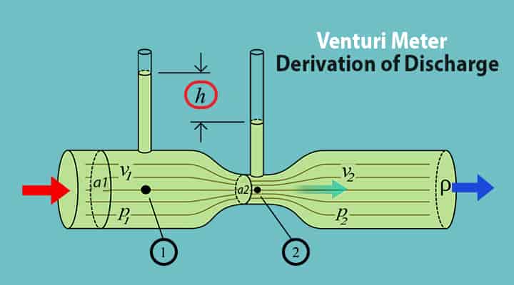
Derivation of Venturimeter or Venturi Tube Discharge
Basic Data: The derivation has been solved on paper because their several rotations cannot be typed here. In the figure, the water flowing in the pipe (flow in) comes with section 1, and flow out goes with section 2.
The several notations are,
- a1 = Inlet area in m2.
- d1 = Diameter of Inlet.
- p1 = Pressure at the inlet in N/m2.
- v1 = Velocity at inlet in m/sec
- d2 = Diameter of the throat.
- a2 = Throat area in m2.
- p2 = Pressure at the throat in N/m2.
- v2 = Velocity at throat in m/sec.
- h = Pressure heads.
- z1 = Elevation at point 1
- z2 = Elevation at point 2
- Cd = Coefficient of Discharge.
- Qact= Discharge at actual in m3/sec.
- Qthe= Discharge (theoretical) in m3/sec.
Theoretical Discharge calculation
Applying Bernoulli’s equation at sections 1 and 2
- p1/ρg + v12/2g + z1 = p2/ρg + v22/2g + z2
As the pipe is horizontal, so, z1 = z2
- p1/ρg + v12/2g = p2/ρg + v22/2g
- p1/ρg – p2/ρg = v22/2g – v12/2g
Therefore, p1/ρg – p2/ρg means the difference of pressure heads at section-1 and section-2, and it is equal to h, hence,
- h = p1/ρg – p2/ρg
- h = v22/2g – v12/2g
- h = (v22 – v12)/2g ——(1)
Now applying the continuity equation at section-1 and section-2,
- a1 x v1 = a2 x v2
- v1 = a2 x v2 / a1 ——-(2)
Substituting this value of v1 in equation (1) and solving, we get
- h = (v22 – v12)/2g
- h = [v22 – (a2 x v2/a1)2]/2g
- 2gh = v22 – (a2 x v2/a1)2
- v22 – (a2 x v2/a1)2 = 2gh
- v22[1 – (a2/a1)2] = 2gh
- v22[(a12 – a22)/a12] = 2gh
- v22 = a12 /(a12 – a22) x 2gh
- v2 = a1/√((a12 – a22) x √2gh

Discharge: Substituting the value of v2 in the above equation
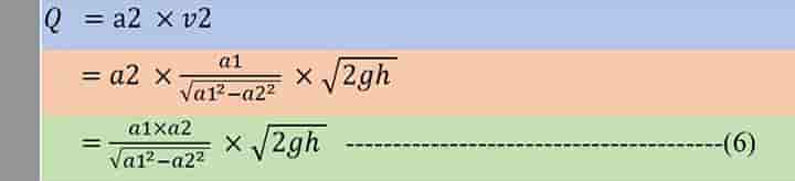
Q is the theoretical discharge under ideal conditions.
Actual Discharge
The actual discharge will be a little different from the theoretical discharge and it is a little less. The actual discharge is given by the formula
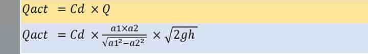
Where Cd is the coefficient of venturi meter and its value is less than 1.
Pressure Differential by Manometer
The other way to find h (Pressure heads) is by using a differential U–Tube Manometer:
We all know, a manometer is having a liquid that is heavier than the fluid flowing in the pipe. This characteristic is used to measure the pressure differential.
- Sh =Heavier liquid specific gravity which is in the manometer.
- hm = Difference of the heavier liquid column in U-tube
- S0 =Flowing fluid specific gravity.
- Sl =Lighter liquid specific gravity.
Condition-1: Liquid in the manometer is heavier than the flowing liquid.
h = hm [Sh/S0) – 1]
Condition-2: The liquid in the manometer is lighter than the flowing fluid in the pipe.
h = hm [1 – (Sl/S0)]
Now, you may wonder how this value is derived? Let’s see the small derivation of this formula.
How to Derive Differential Pressure Head from manometer?
A manometer is used to measure the differential pressure head for a flowing liquid through the pipe.

Let’s derive the differential pressure head for the manometer consisting of heavier liquids in it with respect to the flowing liquid.
- ρm: density of liquid in manometer
- ρ: density of liquid in the pipe
- p1: pressure at the inlet pipe at point 1
- p2: pressure at the throat at point 2
- hm: manometric head that is the different of height between both the column of manometer
- y: height between top of manometer column to the pipe center line.
Let’s consider two-point 1’ & 2’ at the same elevation with the lower column height in the manometer.
- p1’: pressure at point 1’
- p2’: pressure at point 2’
In this diagram, points 1 & 2 are at the same elevation and points 1’ & 2’ also are at the same elevation.
From this diagram, we can say,
- Pressure at 1’ = Pressure at 2’
- p1’ =p2’
Now, we can get the value of p1’ & p2’ from the diagram.
- p1’ = p1 + ρg (hm+y)
- p2’ = p2 + ρghm + ρgy
Equating, p1’ & p2’, we can write,
- p1’ =p2’
- p1 + ρg (hm+y) = p2 + ρm.g.hm + ρgy
- p1 + ρghm + ρgy = p2 + ρm.g.hm + ρgy
- p1 + ρghm = p2 + ρm.g.hm
- p1 – p2 = ρm.g.hm – ρghm
If we divide the equation by ρg, then it will become
- (p1 – p2)/ ρg = (ρm.g.hm – ρghm)/ρg
- (p1 – p2)/ ρg = ρm.g.hm/ ρg – ρghm/ρg
- (p1 – p2)/ ρg = ρm.hm/ ρ – hm
- (p1 – p2)/ ρg = hm (ρm / ρ – 1)
Now, the differential pressure head h = (p1 – p2)/ ρg. So we can write, h = hm (ρm / ρ – 1)
So, the equation of differential pressure head from manometer can be written as
h = hm (ρm / ρ – 1)
This equation can be written as specific gravity as well.
Sh and So are the specific gravity of heavier liquid & flowing fluid.
- Density of liquid = Specific gravity x density of water
- ρm = Sh x 1000
- ρ = So x 1000
Let’s write the equation in terms of specific gravity.
- h = hm (ρm / ρ – 1)
- h = hm [(sh x1000 / So x 1000) – 1]
- h = hm (sh / So – 1)
In the same way, this equation can be written as
- h = hm (1 – Sl / So)
Venturi Meter Animated Video & Explanation
Check out a very nice video to understand the basic concept in visual.
Venturi Meter or Venturi Tube or Venturi Effects Calculation
Let’s try to understand a sample calculation for better understanding,
Venturimeter Solved Problem: Let’s a Venturi meter is placed in a horizontal pipe. The diameter of the inlet section is 20 cm and the throat section is 15 cm. It is installed in a pipe to measure the flow of a liquid. The specific gravity of the liquid is 0.9 and mercury is 13.6. The level of a mercury column in a manometer is 25 cm. Now, we have to calculate the discharge of liquid in lit/hr? Solution in Steps:
Input Data
- Mercury specific gravity, gm = 13.6
- Mercury column, hm = 25cm
- Liquid specific gravity, g = 0.9
- Inlet diameter, a1 = 20cm
- Throat diameter, a2 = 15cm
Calculate Area
- The area of inlet, a1 = (π d1 2)/4 = (π x 400)/4 = 314 cm2
- The area of throat, a2 = (π d2 2)/4 = (π x 225)/4 = 176.6 cm2
Calculate Pressure Differential: The pressure head shall be
- h = hm [( gm / g ) – 1]
- h = 25 [(13.6 / 0.9) – 1]
- h = 352.8 cm of liquid
Calculate Discharge: From Equation Venturi meter of Discharge,
- Q = a1 x a2 /[√(a12-a22) x √(2gh)
- Q = 314 x 176.6 /[√(3142-176.62) x √(2x980x352.8)
- Q = 177634 cm3/sec
- Q = 177.634 lit/sec [1 liter = 1000cm3]
- Q = 2.96 lit/hr.
Cavitation and Venturimeter
Based on the venturi meter design, we have seen that the velocity of the fluid at the throat is maximum which incurs a minimum pressure. Let’s try to understand it,
- Less pressure means it can be even negative or below vapor pressure.
- If it reaches below the vapor pressure, fluid will start to evaporate.
- Bubbles will be formed.
- Cavitation will be started.
Hence, the pressure at the throat point is designed in such a way that it will never reach to vapor pressure.
Standard Venturimeter or Venturi Tube Specification
The main specification points of a standard venturi meter are listed below,
- Specification starts with accuracy! So, how accurate is a Venturi meter? Normally the accuracy of a standard venturi meter can vary from (±) 0.25% to (±) 3.0%.
- The line sizes are normally from 100mm to 800mm. In many cases, it is customized to suit the project requirements as well.
- A standard value of throat diameter to the main pipe diameter ratio (Beta Ratio) is considered in the range of 0.3 to 0.75.
- Normally 75000 is used as the minimum Reynolds number.
In addition to the above, the following details to be given to select a venturi meter,
- Model No.
- Type of fluid.
- Type of application.
- Flow rate.
- Temperature of fluid.
- Viscosity & specific gravity of fluid.
- Size of connection (Inlet and outlet).
- Differential pressure.
- Value of Beta Ratio.
- Material of pipe.
- Material of venturi meter, etc.
End Connections of Venturi Meter
Venturimeter may have the following end connection for pipes:
- Flanged connection
- Welded connections
- Plain end connections
- Mechanical joints, etc.
Materials of Venturimeter or Venturi Tube
Venturi meters can be made of different kinds of materials. It depends on the type of applications or fluids as well as project requirements. Few materials are listed for reference purposes only,
- Aluminum
- Cast Iron
- Carbon Steel
- Stainless Steel
- Duplex SS
- Mild steel
- Chrome Moly
- Titanium
- Hastelloy
- Monel, etc.
Difference between Venturi Meter & Orifice Meter
Now, don’t be confused with the venturi meter with the orifice meter, these two are different items. Which is better Venturi or orifice? What is the difference between the venturi meter and the Orifice meter? Let’s see in brief! A few important differences are captured below to have a basic idea concept of these two,
| Description | Orifice Meter | Venturi Meter |
| Construction & space | Simple design, doesn’t have many parts and space requirement is less | Venturi meter means complex design consisting of different parts and space requirement is large |
| Pressure Loss | High-pressure loss, around 60% | Low-pressure loss, around 10% |
| Pressure loss measurement | By pitot tube | By the inlet & throat size |
| Suitability | Not suitable for slurries | Suitable for slurries |
| Coefficient of discharge, Cd | It less | It is comparatively high |
| Cost | Low cost | High |
| Pipe design | Should be straight | It can be angular |
How to Install a Venturimeter? Installation Guide
The venturimeter is a very small equipment in measurement. Although its small, during its installation, many measures have been kept in mind. Improper installation may impact the measuring parameters and provide incorrect data which creates problem. There are various venturimeter manufacturers available in the market and always their manufacturing guidelines should be opted. Few of guidelines have been illustrated based on our experience:
- Venturi meter should be properly inspected.
- Check the condition of venturi meter, there should not be any problem it.
- Know where to install the venturimeter.
- Know the flow direction. Venturimeter shall be placed considering the direction of flow. Wrong direction will spoil the purpose.
- Installation shall be in such way that there should not be any air pockets and pressure connection should be considered accordingly.
- Installation shall be in such way that there should not be any possibility of condensation and pressure connection should be considered accordingly.
- Venturi meter may be flanged, welded or threaded when it connects with the pipes.
- Piping flanges and venturimeter flanges should be properly aligned.
- Never ever over tightened the bolts for venturimeter flanged fittings.
- In case of flanged fittings, gaskets are used. Check the condition of gaskets and it should be properly centered.
- There should not be any supports for venturi meter.
- All allowances shall be provided for proper installation in line with manufacturing standards or codes.
- Check all the nozzle connections.
- Drain connection should be at lower side, during installation it should be checked.
- During venturimeter installation, straight pipe length shall be checked at inlet (upstrees) and outlet (downstream) at both sides.
- Liquid line should not be pressurized, and liquid should be stable in the line.
- Check the venturi meter if any unused air traps are there, these should be properly closed.
All piping requirements at the inlet and outlet shall be checked as the piping system may have many different connections like:
- Elbows, and it’s plane
- Expander
- Reducer
- T junction
- Valves with open/close scenario
Straight lengths are varied based on the above piping connections.
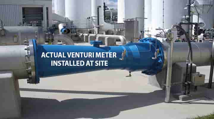
Actual Venturimeter Installation Image
An installed image of the venturi meter is referred to here.
Venturimeter Maintenance
The maintenance of venturimeter is simple as there is no rotating or critical parts. The following maintenance key points needs to be kept in mind:
- Visual inspection at some interval.
- Check if there any leakages.
- Check if process pipes (inlet and outlet pipes) are clean.
- All instrument connections are ok.
- Gaskets are in good conditions.
- Drain lines are not clogged.
- Check if all unused air traps are properly closed.
Applications of Venturi Meter or Venturi Tube
What is venturi meter used for? Venturi Meter is used in various fields like:
- The flow rate of fluid in the pipe is calculated easily.
- The flow rate of suspended solids, gases, slurries, dirty liquids can also be measured.
- It helps to calculate the chemical dosing rate.
- Wastewater treatment flow measuring rate.
- Widely used in large-diameter pipes.
- Used in the waste treatment process.
- High-pressure recovery system.
- It can measure the pressure.
- It can measure the quantity of liquid or gas.
- Medical application, like the flow rate of blood in arteries.
Advantages of Venturi Meter or Venturi Tube or Venturi Effects
The advantages of Venturi Meter or venturi tube or venturi effects are:
- No moving parts & simple operation
- Long term reliability
- Low head loss, as well as energy loss.
- Tolerance of high solids content
- In a high flow rate, it is widely used.
- Pressure recovery is high, around 90%.
- Rarely affected by upstream turbulence.
- Due to the flow, it is normally a self-cleaning device
- It is suitable for cleaning as well
- Rarely affected by erosion
- Rarely get clogged with sediments
- High coefficient of discharge.
- It can be vertical, horizontal, or inclined to suit at the site.
- Very less pressure drop.
- High accuracy
- Suitable for liquid consists of gas, solids, etc.
- This can also be used for a compressible and incompressible fluid.
The pressure recovery is much better for the venturi meter than for the orifice plate.
- It is self-cleaning. In addition to that, this device can be easily be cleaned and remove all dirt, entrants, etc.
- The maximum to minimum flow rate is about 4 to 1
- Very low-pressure loss.
- Highly efficient.
- High viscosity effect.
Disadvantages of Venturi Meter or Venturi Tube
Although there are few disadvantages of Venturi Meter or venturi tube or venturi effects and are as follows:
- Expensive due to the high installation costs.
- The maintenance and as well as cost of maintenance cost is a little high.
- Turn down, i.e., maximum capacity to the minimum capacity is poor.
- Bulky and space constraints.
- Long length requirements.
- Venturi meters are not suitable for small diameter. Roughly it is below 76 mm.
- Limitation of the lower Reynolds number like 150,000.
- Less experimental data are comparative to the orifice plate.
- Cavitation may occur, in case of slight design issues.
Manufacturers of Venturimeter
There are a lot of venturi meter manufacturers available worldwide, few of them are listed,
- HydraCheck,
- Aalborg Instruments & Controls,
- RCM Industries,
- Sierra Instruments,
- Blue-White Industries,
- ERDCO Engineering Corporation,
- Intra Automation,
- Delta Engineering,
Venturi Meter Questions with Answers MCQs
Let’s see a few common venturi meter questions with solutions.
MCQ-1: To measure the flow rate of a fluid through the Venturimeter, it should be installed in direction: (a) Vertical line (b) Horizontal line (c) Inclined line with upward flow (d) In any direction and in any location
Explanation: Ans: (d). Venturimeter does not install at a fixed position, the only condition is that, to measure the flow rate of a fluid, it should pass through the Venturimeter. Generally it installed at the mid point of the pipe.
MCQ-2: Energy loss in flow through nozzle as compared to venturimeter is: (a) Same (b) More (c) Less (d) None of the above.
Explanation: Ans: (a). The nozzle is very similar to venturimeter, the nozzle comes with divergent. Due to similarity, the energy loss is same for both flow rate meter.
MCQ-3: The range of coefficient of discharge (Cd) for venturimeter is given as: (a) 0.5 to 0.6 (b) 0.8 to 0.9 (c) 0.95 to 0.99 (d) 0.7 to 0.8
Explanation: Ans: (c). The Venturimeter is a practical application of Bernoulli’s equation, the discharge Q, can be calculated by, Q = Cd * a1a2 / √(a1² – a2²) * √2gh, Where,
- a1 = area at the inlet of venturimeter
- a2 = area at the throat of venturimeter
- Cd = co-efficient of venturimeter
- h = difference of pressure head in terms of fluid head following through venturimeter.
MCQ-4: Through which of the mathematical expression, the rate of flow by a Venturi-meter is given as: (a) H (b) √H (c) H3/2 (d) H5/2
Explanation: Ans: (b). Flow of venturimeter is given as, Q = Cd * ( A1 A2 ) / ( A1 – A2 ) * √(2gh)
Hence we can say that, the rate of flow through venturimeter occurs in the manner of H1/2.
MCQ-5: The inlet and outlet length of a venturimeter are different and the inlet length of a venturimeter is given as it: (a) Is equal to the outlet length (b) Is more than the outlet length (c) Is less than the outlet length (d) Is independent to the outlet length
Ans: (c)
Standards for Venturi Meters
Let’s see the standards for Venturimeter or venturi tube design,
ISO 5167-3:2003 specifies the geometry and method of use of nozzles and Venturi nozzles
ISO 5167-3:2003 also provides background information for calculating the flow-rate
ISO 5167-3:2003 is applicable to nozzles and Venturi nozzles (Subsonic flow, single-phase fluid).
ISO 5167-3:2003 deals with two types of standard nozzles, the ISA 1932 nozzle, and the long radius nozzle, as well as the Venturi nozzle.
BS 1042-1-1.2 is used closed conduits fluid flow measurements.
ASME MFC-3M is used for installation and flowing conditions.
Standards for venturimeter or venturi tube
Conclusion
Hence, we have learned the basics of the venturi meter, its basic details, along with examples. Please write to us, if you have any doubts.

I love it when folks come together and share views. Great website, stick with it!
Spot on with this write-up, I honestly believe this amazing site needs a lot more attention. I’ll probably be returning to read through more, thanks for the information!