Brayton cycle is explained along with efficiency, T-s, and P-v, diagrams, etc. This article consists of many easy diagrams, explanations, formulas, and examples to clear the basic idea about the Brayton cycle. Let’s explore!
What is Brayton Cycle? Definition
Let’s get into the basic definition of the Brayton cycle, it’s definition, history.
Brayton Cycle Basics
The Brayton cycle is one of the most widely used and famous thermodynamic cycles in gas turbine engines, internal combustion engines, and heat engines.
- The Brayton cycle is a kind of ideal thermodynamic cycle that described the process by which the gas turbine engines or heat engines are undergoing.
- Brayton cycle consists of three main components namely (1) compressor (2) combustor, (3) turbine, and (4) heat exchanger (in case of the closed system)
- All these components undergo compression, combustion, and expansion respectively.
- Different kinds of fuels like oil etc. can be used as heat sources for gas turbine engines.
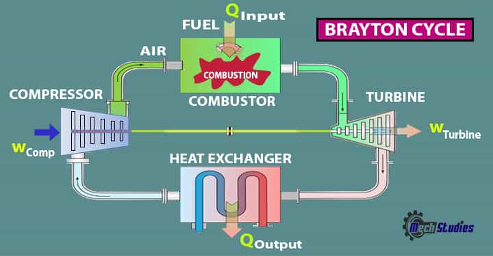
The Brayton cycles are mainly used in jet planes, usefulness of this Cycle is tremendous due to the fact it is the backbone in driving even helicopters, and submarines.
History of Brayton Cycle
The name of this cycle is named after George Brayton that described the working of a constant pressure heat engine in 1872. The original Brayton engine used in the piston compressor, piston expander. But now the modern gas turbine engines are used in air-breathing jet engines. The cycle used in those is generally the open-type Brayton cycle. For the analysis, this cycle is considered a closed cycle. This cycle is sometimes called the Joules cycle also.
Brayton Cycle Definition
It is defined as a cycle, where thermal or heat energy is converted into mechanical energy at a constant pressure. Basically, the Brayton cycle describes the main working process or philosophy of gas turbines or heat engines. The losses in the compressor and turbines and pressure drops in the combustion chambers are neglected in the ideal Brayton cycle for easy calculation.
- The cycle can work in an open system as well as in a closed system.
- In an open loop, the exhaust is to the atmosphere and in a closed system, a heat exchanger is used between turbine and compressor.
So, try to see types, parts, diagrams, actual cycles, etc.
Types of Brayton Cycle
Normally, two processes can be used,
- Open cycle: one is open to atmosphere and uses the internal combustion chamber,
- Closed cycle: the other type is the closed one and it uses the heat exchanger.
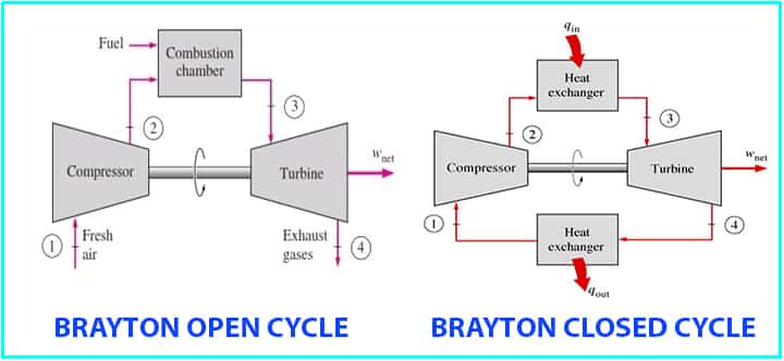
Brayton cycle is the most common cycle known and describes the working of the constant pressure heat engines. The ideal Brayton cycle consists of two isentropic processes and two isobaric processes alternatively. Let’s check out the components and processes.
Brayton Cycle Parts & Diagram
Let’s see the Brayton cycle parts along with a basic diagram.
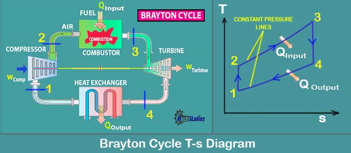
There are four main components,
- Compressor (C)
- Combustor or Combustion Chamber (CC)
- Turbine (T)
- Heat Exchanger (HE)
Compressor
- The compressor draws the ambient air
- Compression happens, which means pressure & temperature is increased
Combustor
- Basically fuel injection is done in the combustor or mixing chamber
- Combustion happens in (hot air+fuel) the mixing chamber
Turbine
- Here, air releases its energy
- Expansion happens in the turbine and work is created
Heat Exchanger
- Basically, heat is rejected to the atmosphere from the heat exchanger.
So, try to see we will see a typical ideal Brayton cycle its processes, and some of its variations. In addition, where are the differences between the actual cycle and the ideal cycle?
Ideal Brayton Cycle Processes with T-S & P-v
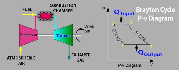
In the ideal Brayton cycle, there are four processes running, we will check each of them and what will happen in each process. Let’s delve into the T-S diagram for a better explanation.
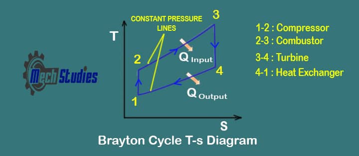
Process 1-2 Isentropic compression process
In this process, the working gas is compressed adiabatically from state 1 to state 2 with the help of a compressor.
- The process is done by keeping the entropy constant and increasing its internal energy and internal pressure.
- The work required for the compressed can be given by the equation Wcomp = h2 – h1.
Process 2-3 Isobaric heat addition process
In this process, the heat is added at constant pressure i.e. isobaric process.
- The gas is heated using an external heat source and the gas is heated at constant pressure.
- The heat addition can be calculated by the equation Qinput = h3 –h2.
Process 3-4 Isentropic expansion process
In the isentropic expansion process, the heated gas will be expanded adiabatically from the state 3 to 4 in a turbine.
- The gas will do the work and will lose the amount of energy that is equal to the work that will leave the system.
- It can be calculated by using the equation, WTurbine=h4 – h3.
Process 4-1 Isobaric heat rejection
In this process, the expanded gas will have its heat rejection from state 4 to state 1. This process will be completed at constant pressure.
- The working gas temperature will drop from state 4 to state 1 and cycle will be completed.
- It can be calculated with the help of equation QOutput=h4 – h1.
During a Brayton cycle, work is done on the gas by the compressor between states 1 and 2 (isentropic compression). Work is done by the gas in the turbine between stages 3 and 4 (isentropic expansion).
The difference between the work done by the gas and the work done on the gas is the network produced by the cycle and it corresponds to the area enclosed by the cycle curve (in Pv diagram below). So, these are the four processes in the ideal Brayton cycle.
Brayton Cycle with P-v Diagram
Let’s see the P-v diagram,
Brayton Cycle Equations or Formula
Let’s find out the Brayton cycle efficiency,
Brayton cycle efficiency = WNet / QInput
Where,
- WNet is the network output from Turbine
- QInput is the heat input from the combustor
Let’s consider the following,
- T1: Temperature at point 1
- T2: Temperature at point 2
- T3: Temperature at point 3
- T4: Temperature at point 4
- WComp: Work done on the compressor
- QCC: Heat input to the combustion chamber
- Wturbine: Work produced by the turbine
- QExchanger or Qoutput: Exhaust heat from the heat exchanger
- m: Mass flow rate
- ηTurbine: Compressor Efficiency
- ηComp: Efficiency of Turbine
Then we can write,
- QCombustor = m Cp (T3-T2) = QInput
- QExchanger = m Cp (T4-T1)
- WPump/m = h2-h1
- WTurbine/m = h3-h4
Wnet = WTurbine – Wcompressor = QOutput =m Cp (T4-T1)
Brayton cycle efficiency = WNet / QInput
Hence, η
- η = WNet / QInput
- η = 1 − QExchanger / QInput
- η = 1 – [ m x Cp x (T4 – T1)] / [ m x Cp x (T3 – T2)]
- η = 1 – [ T1 x (T4/T1 – 1)] / [ T2 x (T3/T2 – 1)]
From the equation of isentropic process, we can write,
T2/T1 =(P2/P1)(k-1)/k = (P3/P4)(k-1)/k =T3/T4
Hence,
- T2/T1 = T3/T4
- or T4/T1 = T3/T2
From isentropic efficiency, we can write,
η = 1 – T1/T2 = T4/T3
If the pressure ratio is rp, then,
rp =P2/P1 = P3/P4
Hence, we can conclude,
η = 1 – rp(1-k)/k
Actual Brayton Cycle
So, as with any other ideal process, the actual process differs from the ideal process. The ideal process is assumed to make the calculations and setting a specific standard. In the actual cycle,
- Losses are considered
- Pressure drops are considered
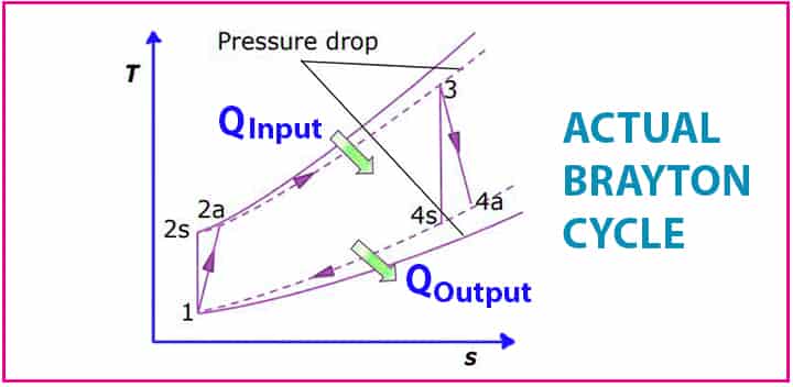
We have seen the compression, as well as expansion process, are isentropic in the ideal Brayton cycle.
- But in actual it doesn’t happen, also the same case for the isentropic expansions.
- Both the compression and expansion increase the entropy it doesn’t remain constant.
- Irreversibility exists in the actual Brayton cycle.
- There is a slight deviation in the compressor.
- Pressure drop occurs in the mixing chamber
- Also, a slight deviation happens in the turbine too.
- Also, in the expansion process as the work is generated is equal to the supply in case of the ideal Brayton cycle.
- But in the actual cycle, there are some losses that don’t allow the net output to be the same as that of the supply.
Actual efficiency shall be as follows,
- nc = h2s-h1/h2a-h1
- nt =h3-h4a/h3-h4s
Where,
- nc = actual efficiency of the compressor
- nt = actual efficiency of the turbine
- h1, h3 = Enthalpy at respective points
- h2s, h4s, = Isentropic Enthalpy at respective points
- h2a, h4a, = Actual Enthalpy at respective points
There are some ways to increase the net output as well as the efficiency in the Brayton cycle. Like, to increase the power reheating of the working fluid and overspray methods are employed. In case of improving the efficiency, increasing pressure ratio, recuperator, and co-generation system are used.
So, there are two basic processes to overcome the losses as well as to increase the power output in the Brayton cycle. We will diagrams as well for the below process,
- Brayton cycle with reheat
- Brayton cycle with regeneration
Brayton Cycle with Reheat
In case of the Brayton reheat cycle, two turbines will be kept in a series. The first turbine receives the hot gas from the combustor and a reheat combustor is provided between these two turbines.
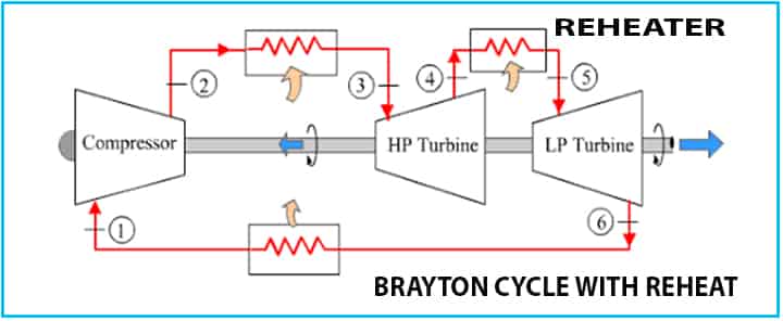
- This reheat increases the work output from the turbines, as there are two turbines.
- Additional heat for the reheater is required.
- Efficiency normally increases slightly, but it may not be increased all the time.
The reheating method helps to reduce the condensation during the expansion and it helps to reduce the probability of damaging turbine blades.
Brayton Cycle with Regeneration
The name Regeneration means the extract heats will be reused to heat the air after the compressor.
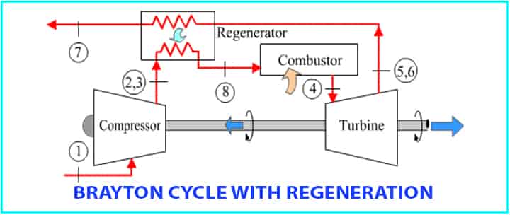
- The extracted heat is taking in the regenerator.
- Efficiency will be increased.
Brayton Cycle Examples
In the gas turbine, the Brayton cycle is used to produce work. Here, ambient air is introduced to the compressor, and pressure and temperature are increased by the compression process. After compression, hot air is passed to a mixing chamber and fuel is injected. In this chamber, combustion happens and later on, hot gas is passed through the turbine and expansion happens. This expansion helps to produce energy or work which drives the gas turbine. The details of the gas turbine are captured in our separate article.
Conclusion
Hence, we have learned the basic idea of the Brayton cycle along with various diagrams, etc. T-s and P-v diagram also explained to simplify the Brayton cycle. Any questions, please write to us or comment in the below comment box. Happy learning!

