Steam turbines are explained along with its definition, parts, types, how does steam turbines work, advantages, disadvantages, application, etc.
Let’s explore the Steam Turbine!
What are Steam Turbines?
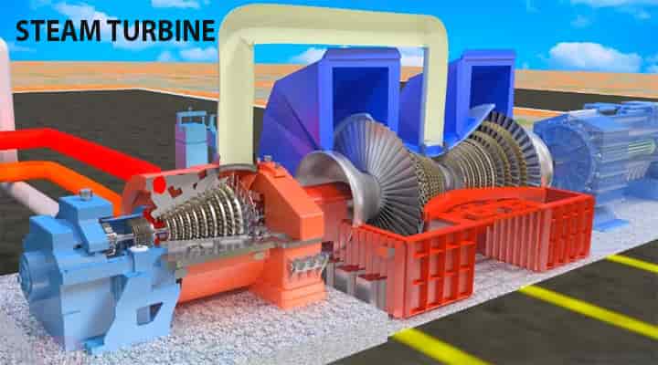
Let’s get into the steam turbine! The turbines are used in every possible sector nowadays. There are various types of turbines available nowadays. Like, gas turbines, wind turbines, steam turbines, hydraulic turbines, etc. The steam turbine is one of the most used in power stations and factories.
- Basically, the steam turbine is a prime mover that transfers one energy to the other.
- In the case of gas turbines, it transfers the impinging energy from gases on rotor blades to the mechanical rotating energy and further conversions take place.
- But in the steam turbine, it converts the thermal or potential energy of the steam into kinetic energy and then in the mechanical energy in the form of rotation of turbine shafts.
The steam turbine has different parts that accommodate the working of the steam turbines. Steam turbine ability is it can develop high power even in the small space. The steam turbine is now superior to all the turbines available except the hydraulic turbines. There are various types of turbines available and they are classified into various different types according to some specifics.
Let’s see the classification of the steam turbines to understand them better.
Types of Steam Turbines
Steam turbines are classified based on the following,
- Action of steam
- Stages
- Steam flow type
- Numbers of shaft
- Governing methods
- Heat drop process
- Steam conditions
- Applications
According to the action of steam
- Impulse turbine – examples De-Laval, Curtis and Rateau
- Reaction turbine
- Combination of impulse and reaction turbines (Compound turbines)
According to stages
- Single-stage turbines
- Multistage impulse and reaction turbines
According to type of steam flow
- Axial turbines
- Radial turbines
Number of shafts
- Single shaft turbines
- Multi-shaft turbines
Method of governing
- Throttle governed
- Nozzle governed
- By-pass governed
Heat drop process
- Condensing turbine with generators
- Condensing turbines with one or more intermediate stage extractions
- Back pressure turbines
- Topping turbines
According to steam conditions from inlet to outlet
- Low-pressure turbines – 1.2 – 2
- Medium pressure turbines – up to 40 atmospheric absolute pressure
- High pressure turbines – Above 40 atmospheric absolute pressure
Applications
- Stationery turbines with a constant speed of rotation
- Stationery turbines with the speed of rotation
- Non-stationery turbines with variable speed
These are all the detailed classifications of steam turbines.
The main basic types are,
- Impulse turbines and
- Reaction turbines.
First, we will get to know about the parts or components of the steam turbines and then we will see the impulse and reaction turbines.
Parts of Steam Turbines
The components of the steam turbines are as follows,
- Nozzles,
- Wheel or rotor,
- Blades or vanes
- Protective casing
- Sealing
- Bearing
- Governor system
- Overspeed trip system etc.

Let’s know it one by one.
Nozzle
The nozzle is the equipment that has a convergent shape structure. The high-pressure steam coming from the boiler enters the convergent-shaped nozzle.
- The steam gets expanded in the nozzle and high pressurized and relatively low-velocity steam gets available at the entry section of the nozzle.
- Due to the convergent shape of the nozzle, the velocity increases at the exit of the nozzle.
- The velocity of the steam is increased. Hence the high-velocity steam is further transferred.
Rotors
The rotor or in simple words a wheel is mounted on the shaft. The mounting of the rotor on the bearing to get a smooth and effective rotation.
- The rotors are equipped with blades.
- A high-velocity jet coming from the nozzle has impinged on the blades that move the rotor.
- The rotors are shrouded from the top to keep the blades in the position also steam should not leave due to centrifugal action.
Blades
The rotors are equipped with the blades in convex shapes. A passage is formed between the two consecutive blades.
- The high-velocity steam coming from the nozzle has impinged on the blades.
- This high-velocity jet creates a tangential force on the blades.
- It makes the blades move but the blades are stationary and mounted on the rotors so the rotor rotates.
- To minimize friction loss the blade’s surface is made smooth.
Protective Casing
The name suggests itself the casing encloses all the parts of the turbine. It covers the rotor and blades assembly.
- The nozzle is attached to the casing and the casing made separate from the rotor by introducing packing or oil seal.
- It results in running shaft freely and prevents leakage.
Sealing
Steam turbine shall consist of the proper sealing system to avert any leakage.
- The labyrinth is used to reduce the leakage from the high-pressure side to the low-pressure side of the steam turbine.
- Clearance is kept minimum as little as possible between labyrinth and shaft.
- Carbon ring sealing is used between the casing and the shaft to seal.
Bearing
Bearing is used to supports the rotor and protective casing.
- The bearing cases consist of journal bearings.
- It is sealed to prevent oil leakage toward the outside.
- It also prevents the ingress of water, steam, dust, etc.
Governor System
The steam turbine is having a governor system to control the speed of the turbine. It consists of a valve that is a governor valve or steam valve and an interconnecting linkage.
- It is done by control the stream flow rate through the turbine.
- This flow rate is controlled by the governor valve.
- The governor is able to sense the speed of the turbine shaft & control it accordingly.
Overspeed Trip System
As the name suggests, it is a system to stop the steam flow into the turbine with the help of a different quick-closing valve and a linkage.
Now we have known the parts of the steam turbines.
For details, you can refer mathematical calculation
Check out a very nice ANIMATED VIDEO
from Technical Engineering School!
How Does Steam Turbines Work?
Steam Turbine Basics
The steam turbine is the heart of the thermodynamic cycle, called the Rankine cycle. We have already learned that Rankine cycle consists of main four components,
In this cycle, the working fluid is water which follows the process as below,
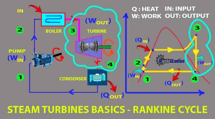
- Normal-pressure water from the condenser.
- Pressurized Water to Boiler through the pump.
- Pressurized water to dry saturated steam in the boiler.
- After that, Isentropic expansion (Point 3-4) happens in the steam turbine.
- In this process, expansion happens in the turbine as dry saturated steam enters & hits the blades.
- This process basically for power output.
- As per the Rankine cycle, this work output will ve, Wout= h3-h4 [h3 & h4 = enthalphy at point 3 & 4 respectively]
- All processes in the Rankine Cycle including work input, work out, heat input & heat out, etc. are captured in the steam turbine Rankine cycle.
How Does Steam Turbine Work?
The working principle of a steam turbine is very simple.
Let us try to refer to the steps.
Step-1: Steam has thermal energy. Steam turbines are operated with high-pressure steam. Steam turbines have a series of blades and all blades are airfoil type.
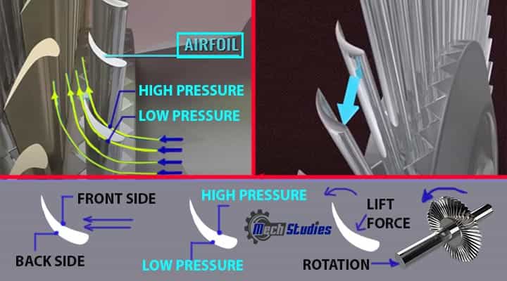
- Front side of blade: Steam direct hits and create high pressure.
- Backside of the blade: Steam is not directly hit this portion so pressure is low comparative to the front side.
Due to this uneven pressure in the front & backside, a pressure differential is formed in the blade.
Step-2: Pressure differential creates lift force on the blade and the blade starts to rotate.
Step-3: This rotation helps to convert the thermal energy of the steam into kinetic energy. As blades rotate, the rotor, where blades are mounted, also starts to rotate.
Here, due to the strike of steam into blades, the following parameters are reduced,
- kinetic energy of steam,
- pressure of steam,
- temperature of steam,
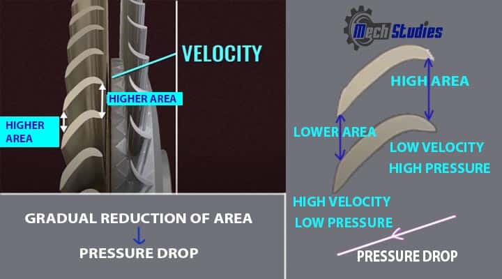
Step-4: To remove this energy reduction, another series of stators is introduced in front of the blades. This rotor acts as a diffuser that is varying cross-sectional area from higher to lower.
- Lower area implies higher velocity
- Higher velocity means a reduction in pressure from Bernoulli’s equation.
Step-5: This reduction of pressure, implies a higher volume, as per Gas Law. [P ∝ 1/V]. Now, to accommodate this high volume, a series of blades and stators are required and steam turbine worked.
Step-6: In case of a large thermal power plant, or steam turbine plant, turbine are segregated into three parts,
- High pressure turbine (HP)
- Intermediate Pressure Turbine (IP)
- Low Pressure Turbine (LP)
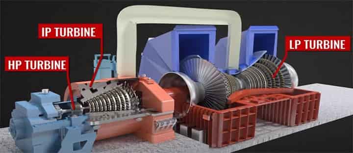
To get the optimum energy, blades are suitable designed and angled. A governing section is provided before the turbine to control the flow of steam as well as control the power output.
Description of Important Steam Turbine
Let’s take a look at the impulse turbines. The impulse turbines are single-stage turbines and they are suitable for low-pressure steam.
- Impulse steam turbine
- Reaction steam turbine
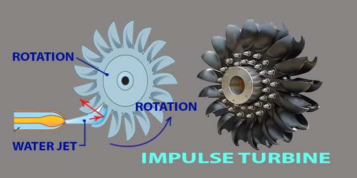
Impulse Turbine
The impulse turbine is also called as De-Laval turbine. It is a simple impulse turbine in which the expansion of steam takes place in one set of nozzles.
- In the case of the impulse turbines, the pressure drop is only happening in the nozzle.
- The pressure throughout is constant while steam is flowing over the moving blades.
So, in the nozzle the steam is expanded initially it can be one nozzle or set of nozzles. The set of nozzles can be placed with a gap of 5-6 meters.
The high pressurized steam is transferred from the boiler to the nozzle and then it gets expanded at the entry and creates a high-velocity jet at the exit of the nozzle.
- When the steam leaves the nozzle, it has high velocity and it strikes the blade.
- Hence the loss of energy occurs due to high exit velocity and it’s known as the carry-over loss or leaving loss.
- It can be about 3-4% of nozzle outlet velocity.
- The high-velocity jet is captured by the blades and hence blade velocity is high about 25000 to 3000 RPMs.
This much speed can be unstable if we talk about balance. But there is a way of reducing these speeds by the method of compounding. Obviously, this high speed is not practical and can cause various failures.
The speed can be corrected by the methods like
- velocity compounding (Curtis turbines),
- pressure compounding (Rateau turbines), and
- the combination of the pressure as well as velocity compounding.
Let’s check them in brief.
Pressure Compounding of Steam Turbines
In case of the pressure compounded turbines, the number of impulse turbines are lined up in series arrangements. All these impulse turbines are arranged on the same common shaft.
- Also, the nozzles are fixed at the entry of each impulse turbines.
- The arrangement is like one set of nozzles and one set of impulse turbine and so on.
So, as we have already known the pressure drop first gets in the nozzles. Now if the nozzle is divided as per the above pressure compounding arrangement, we can reduce the speed, right?
- Here is more explanation, when the steam comes in the first arrangement of nozzles a small pressure drop will occur.
- This kinetic energized steam will go to the next row and the kinetic energy will be absorbed.
This cycle of pressure drops and kinetic energy absorption continues till the steam pressure becomes the exhaust pressure.
Velocity Compounding of Steam Turbines
Now in the case of the velocity compounding of the steam turbines, one set of nozzles and two more rows of moving blades are arranged in the series arrangements.
But in between the two moving blades, there are one set of guide vanes.
- The moving blades and the fixed blades are arranged in different placements.
- If moving blades are arranged directing one side the fixed blades will be directing the another.
- The high-velocity stream of steam jet enters the first moving blades, here some portion of the velocity is absorbed.
Now as per the arrangement the stream will enter the fixed blades and the direction will be changed which will suit the next row of moving blades. Now again here the velocity will be decreased.
This method was proposed by C.G. Curtis and used in the Curtis turbine.
Pressure Velocity Compounding
If the pressure is much larger the combination of pressure velocity compounding will be suitable.
- In the pressure velocity compounding the first pressure drop will be seen in the first set of nozzles.
- Now the kinetic energy gained will be used in the upcoming two rows of moving blades.
The kinetic energy gain will be used in the two moving blades before getting towards the second pressure drop. The cycle will be repeated.
Reaction Turbines
The reaction turbine is the one in which the steam pressure will decrease gradually. It will decrease gradually while expanding the steam through the moving as well as the fixed blades.
This is the simple meaning or definition of reaction turbines.
- The reaction turbines have a number of stages containing the sets of fixed blades and moving blades.
- One thing to note the pressure dropped in the nozzle only partially. The work of the nozzles is done by the fixed blades.
- They increase the steam velocity as per the work of the nozzle and also directs them to enter the sets of moving blades.
- All the blades are nozzle shaped obviously to do the nozzle work thingy.
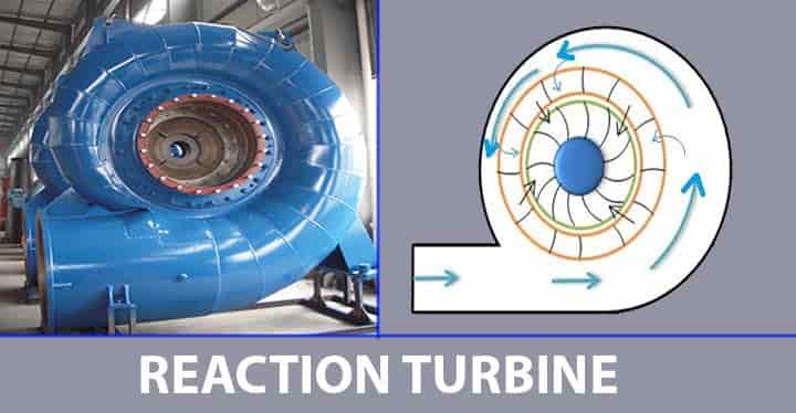
So, the steam will expand on moving blades and it will give the reaction to the moving blades. Fixed blades are mounted on the casing and the moving blades are fixed with the rotors.
Now we have known both impulse and reaction turbines. Now it’s time for knowing the difference between the impulse and reaction turbines.
Difference between Impulse and Reaction Turbines
Let us see the difference between impulse & reaction turbines,
| Impulse turbine | Reaction turbine |
| In case of the impulse turbine steam expands in the nozzle and pressure is constant while flowing the steam through blade passages. | In case of the reaction turbine the steam expands partially in nozzle and expansion takes place in the rotor blades. |
| Blades are symmetrical. | Blades are asymmetrical. |
| Both ends pressure on moving blades is the same. | Both ends pressure on moving blades is different. |
| High steam velocity. | Comparatively steam velocity is not high. |
| High speed. | Comparatively low speed. |
| The same power developed in the impulse turbine because the pressure drop is more, the number of stages required are less. | The same power developed in the reaction turbine because the pressure drop is low, the number of stages required are more. |
| Blade efficiency curve is less flat. | Blade efficiency curve is flatter. |
Advantages of Steam Turbines
The advantages of a steam turbine are as follows,
- The reliability of steam turbines is more, especially where high power is needed.
- Steam turbines require less mass flow rates compared to gas turbines.
- High power to weight ratio compared to reciprocating engines.
- Less moving parts than the reciprocating engines.
- Steam turbine has less vibrations.
- Thermal efficiency is high compared to reciprocating engines.
- Suitable for large thermal power plants.
- Steam turbines are used in large-capacity thermal power plants.
Disadvantages of Steam Turbines
Disadvantages of a steam turbine are, as follows,
- Relatively the overnight cost is more.
- At part-load operation, steam turbines fall behind reciprocating engines.
- Longer startups than gas turbines.
- Frictional loss occurs in the nozzle,
- Loss occurs due to the separation of layers, mechanical friction, leakage, etc.
- Corrosion & erosion happens in the turbines
- Vibration, as well as noise, is an issue in case of slight misalignment.
- Responsiveness to changes in power demand is less compared to gas turbines and reciprocating engines.
Applications of Steam Turbines
The application of steam turbine is, as follows
- Steam turbines are used in the chemical industries for providing heat and electricity for driving different processes.
- In pharmaceutical industries for producing power.
- Steam turbines due to their sustainable and stable operations they are used in the sugar mills extensively.
- Used to drive the compressor or as a pump drive in the oil and gas industries.
- In most large-scale thermal power plants, steam turbines are used.
The steam turbines can be seen mostly in power industries these days. Due to it’s advantages over gas turbines they are used extensively.
Steam Turbine vs Gas Turbine
The differences between the steam turbines and gas turbines are tabulated, as below,
| Sr. no | Steam turbine | Gas turbine |
| 1 | Steam is the main working fluid. Water is heated and steam is formed & expand in the steam turbine to produce work or electricity | Natural gas is used, which is undergone combustion process and produce hot gas. The same gas expands in the gas turbine to produce work or electricity. |
| 2 | Steam turbine works based on the Rankine Cycle. | Gas turbine works based on the Brayton’s cycle. |
| 3 | Steam temperature reaches in the range of 500 deg. C to 650 deg. C | Hot gas temperature reaches around 1500 deg. C. |
| 4 | It doesn’t have combustion system | It has combustion system |
| 5 | No air induction in the system | Air induction is essential for combustion |
| 6 | No intercooler is required. | Intercooler is required. |
| 7 | Less noise, as no air entry | Comparatively high noise due to air entry. |
| 8 | There is a chance of freezing at the centrality due to low pressure. | No chance of freezing. |
| 9 | No fossil fuel is required for steam turbine | Fossil fuel is mandatory. |
| 10 | Doesn’t create pollutants, | It creates pollutants like nitrogen oxide. |
Standard Design Data of Steam Turbines
- First critical speeds of the Turbine rotor
- Second critical speeds of the Turbine rotor
- Turbine max output
- Turbine rated output
- Numbers of stages
- Efficiency of turbine
- Diameter of the tips of the first row of blades
- Diameter of the tips of last row of blades
- Erosion protection due to moisture impingement
- Materials of Construction of Turbine casing, Turbine rotor, moving & fixed blades, Guide blade carriers
- Design Pressure and Temperature for HP, IP & LP Turbine
- Details of Bearings
- Details of diaphragm
- Details of Couplings
- Details of Casing Bolts
- Type of governing system
Steam Turbine Protective Devices
- Casing expansion
- Over speed trip
- The steam flow control device
- Tripping Device
- Low Lube Oil Pressure
- Low Vacuum
- Temperature trip
- HP/IP/LP turbine trip
- Vibration monitoring
- Shaft displacement monitoring
- Casting temperature trip
- Rotor temperature trip
- Bearing temperature trip
- Manual as well as a remote trip
Steam Turbine Project Examples
There are so many steam turbines are installed in the various power projects.
Few of them are listed for reference,
- 2×525 MW Thermal Power plant in Maithon, West Bengal used steam turbines.
- 2×600 MW Thermal Power plant in Raghunathpur, West Bengal used steam turbines.
- 2×300 MW Chandrapur Thermal Power Project used steam turbines.
- 2×660 MW Mundra Supercritical Power Plant, Gujrat.
- 6×210 MW Kolaghat Thermal Power Station, West Bengal
- 2×500 MW & 3×200 MW Thermal Power Station, Farakka, West bengal
Standards of Steam Turbines
There are many standards available for steam turbines, like
- API 611
- API 612
- ISO 14661:2000(en), etc.
Manufacturers of Steam Turbines
Few of manufacturers are listed for reference only,
- BHEL (Bharat Heavy Electricals Limited)
- Shanghai Electric
- Alstom
- GE Power
- Siemens Energy
- Mitsubishi Heavy Industries etc.
High Rated Course
Intro to Fluid Mechanics for Engineering Students Part 1
Intro to Fluid Mechanics for Engineering Students Part 2
Conclusion
Hence, we have learned the basics of steam turbines, its different parts, working principles, how does steam turbines work, etc. Any doubt, please let us know.
Further Study
Reference Articles