In this article, we will learn the basics of gear pumps, along with the definition, internal & external gear pump types, working procedure, applications.
Let’s explore!
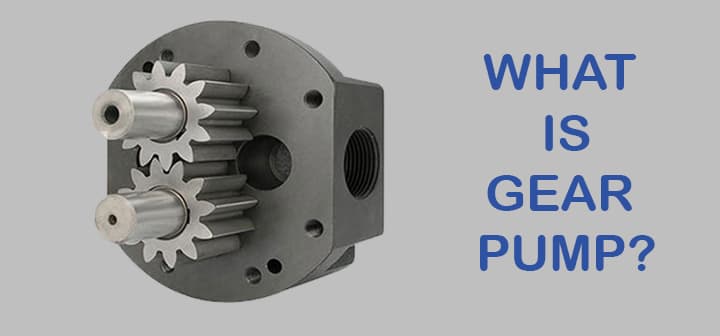
What are gear Pumps? Definition
Let’s try to understand the gear pumps with simple basics and definition.
Gear Pump Basics
We all use a pump in our daily lives, especially to fill tanks on our house’s terrace. The pump has many types depending on construction and application.
- It is a mechanical device that is used to deliver pressurized fluid at the required quantity.
- A pump is needed to deliver specific fluid at specific pressure at specific discharge.
- Pump mainly convert mechanical energy into hydraulic energy.
- Electrical energy is used generally to move the prime mover.
Pumps mainly do these two things – they circulate fluid in a system or they move liquid from one place to another. Gear pump is also do the same thing. So, what is a geap pump?
Gear Pump Definition
Gear pump can be defined as follows,
A Gear Pump is one kind of pump which converts mechanical energy into hydraulic energy with the help of gear networks.
Check out our ‘MechStudies – The Learning App’ in iOS
& Android
Parts of Gear Pumps
There are a few parts of the gear pump, as follows
- Prime mover
- Drive gear
- Driven gear
- Gear pump casing
- Pump inlet
- Pump outlet
- Safety valve
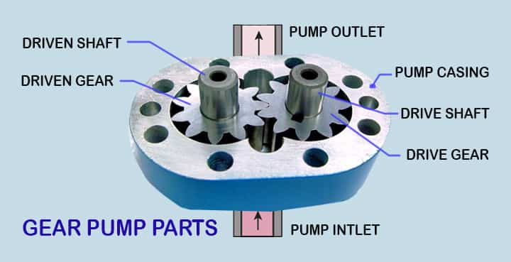
Prime Mover
- Prime mover is the main source of power to the gear pump.
- It can be various equipment, like motor or engine, etc.
- The shaft of prime mover is connected to the gear pump through a drive shaft.
Driver Gear
- A drive gear is mounted on the drive shaft.
- Drive gear is connectde to the prime mover.
- Drive gear rotates when the prime mover rotates.
Driven Gear
- The driven gear means the gear which will be driven by drive gear.
- It is in the loop with drive gear.
- If drive gear rotates, driven gear will also roates.
- It is also called as idle gear as well.
Gear pump casing
- Pump gears are installed within a casing.
- The material of gear pump casing shall be based on the applications.
Pump Inlet
- Gear pump inlet means the portion through which fluid enters into the pump.
- It is basically the suction side of pump.
- Low pressure is created in this section & fluid is sucked by the pump.
Pump Outlet
- This is the discharge side of pump.
- High pressure fluid leaves the pump to the destination.
Safety Valve or Release Valve
- Safety valve in gear pump is mandatory to release the exces pressure.
- Without safety valve, pump can be damaged.
Types of Gear Pumps
To understand the type of gear pumps, let’s try to understand the pump broad classification. Pumps are classified into two types-
- Positive displacement pump
- Dynamic pressure pump
Dynamic pressure pumps are centrifugal pumps. These are used to provide high discharge and low pressure.
Positive displacement pumps are further divided into the rotary pump and reciprocating pump.
Reciprocating pump
The pumping is done by the to and fro motion of the piston. It is used where a small quantity is to be delivered.
- Piston pump
- Diaphragm pump
Rotary pump
This pump’s working is based on rotary motion.
- Gear pump
- Lobe pump
- Ge-rotor pump
- Screw pump
- Vane pump
Now, here we will discuss the gear pumps in detail! Normally, gear pumps can be classified into the following types,
- External Gear Pump
- Internal Gear Pump
- Lobe pump or lobe gear pump
- Ge-rotor pump (Generated Rotor)
Positive displacement is those which displace fix amount of fluid at each cycle. This is done by changing the volume on each scale. Discharge is calculated by-product of displacement per cycle and its rotation in rpm.
The flow capacity is dependent on the design, size, and operating speed of the pump.
The pressure that the pump delivers mainly depends upon the flow resistance of the system in which the pump is installed and is affected only by the size of the prime mover which is an electric motor and the strength of the parts used.
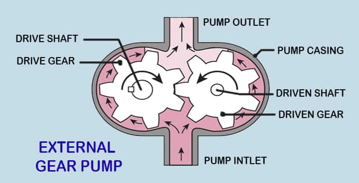
External Gear Pump
What is External Gear Pump?
These pumps are a favorite choice for fluid power transfer unit or as lubrication pump in machine tools. The oil pump is one of the most common applications.
- They can be of one set of gear or two sets of gear configuration as per the need.
- Spur and helical gear are generally used but herringbone gear can also be used when the application demands smoother flow.
- Large capacity pumps mainly use helical gears or herringbone gear.
- They usually operate between 1500-3500 rpm and pressure achieved can be up to 200 bar.
- Due to these specifications, they are preferred for hydraulic operations.
- But they are not suitable for abrasive as well as high-temperature conditions.
As internal clearance provides detailed information on spacing in a pump, reliable data can be obtained about the flow of fluid through it. Which in turn provides better flow control and gives precise transfer.
Hence they can also be used in metering applications. Fuels and chemical agents are also transferred using this as they provide precise control.
Parts of External Gear Pump
This type of pump is famous for its compact size. One big casing is provided. Inside this casing, there are 2 gears.
These gears are generally spur gear or helical gear depending upon the application and size constraints.
- These two gears are in mesh with each other.
- As they are mounted inside a casing, very minimum clearance is provided between them and the casing to avoid friction and wear of gear.
- One gear is a driver as it is connected to the prime mover while the other is driven gear which rotates is it in mesh with driver gear.
- So the whole system is simple, when the prime mover starts to rotate the driver gear the driven gear will also rotate as speed is transmitted.
- If driver gear rotates in a clockwise direction then the driven gear will rotate in an anti-clockwise direction.
How Does External Gear Pump Work?
When both gears start to rotate, a partial vacuum is created at the inlet pump.
- Due to this oil or any liquid which is stored outside at atmospheric pressure rushes in as it is forced due to pressure difference.
- Now, this oil gets trapped into the pockets between the gear and casing.
- During the initial position when oil enters the pump it gets pressed into pockets.
- It then pressurized as gear forces it on the casing.
- As the gear rotates it gets dragged with it and finally, it reaches the outlet. As inside pressure is more than outside it rushes out.
This way oil gets delivered from inlet to outlet. This process is happening on both sides of the gears that are in contact with the casing.
They are also known as fixed displacement pumps as the pump ejects a fixed quantity of fluid per revolution of the shaft.
Advantages of External gear Pump
- It has high speed.
- It provides high pressure.
- There is no overhung bearing load on it.
- In terms of noise, it is relatively quiet in operation.
- Various types of material can be used for delivery.
- It is bidirectional. Hence it can be rotated clockwise as well as counter clockwise.
Limitations of External gear Pump
- No solid can be pumped.
- It has fixed end clearance.
- Four bushings are needed in the liquid area.
Applications of External Gear Pump
- To transfer various lube oils and fuel.
- Chemical additive agents and polymer transfer metering.
- Chemical agent mixing or blending operation.
- Industrial hydraulic applications.
- Low volume high pressure delivery.
- Acid and other harmful corrosive substances can also be pumped.
- Agriculture, mining machinery.
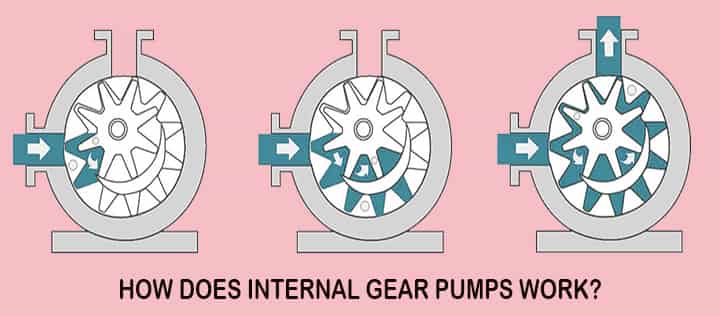
Internal Gear Pump
What is Internal Gear Pump?
It can be worked with variable speed. They have high reliability for long service life.
As the presence of fewer moving parts, it makes such pumps easy to maintain and needs less maintenance cost.
Parts of Internal Gear Pump
This pump is a little bit complex in construction. There is one casing, inside it, there are two gears.
- Namely external gear and the internal gear. An external gear has teeth from the outside.
- While internal gear is the one that has teeth from inside. An external gear is inside of the internal gear.
- Both these gears are in mesh together.
- A crescent seal is situated between these gears. Its function is to fill the gap present between these gears.
How Does Internal Gear Pump Work?
Oil is maintained at atmospheric pressure outside. When these gear starts rotating partial vacuum gets created at the inlet and outside oil flushes in.
- This partial vacuum is created as both gears are in mesh, when they come out extra space is created between that cavity which gives rise to a partial vacuum.
- As soon as oil moves into this gap, it gets trapped between the external and internal gear teeth.
- As the external gear rotates it oil gets carried away within that cavity.
- During this whole process, the pressure gets increased.
- Oil is continuously subjected to pressure and size of cavity goes on decreasing, as it has no place to go its pressure increases.
- When outlet approaches this oil rushes out with high speed and pressure.
Advantages of Internal gear Pump
- They generate high pressure in one stage.
- It had a simple and compact design.
- Sometimes cavitation is resisted by it in certain fluids.
- It has very low noise levels,
- The pump can be used in bidirectional mode.
- Pressure and flow pulsations are generally minimum.
- These pumps can be used in variable speed drive configurations.
Limitations of Internal gear Pump
- Solid and sludge type material cannot be pumped.
Applications of Internal gear Pump
- It is used in hydraulic presses.
- Also used in injection molding machines.
- Machine and power tools.
- It is also widely used in elevators.
- As it provides high pressure, it is used in pressure die-casting machines.
- Their high pressure delivery makes them suitable for hydraulic power units.
- Plastic and polymer processors.
Lobe pump
It is a rotary type of pump. It resembles a gear pump in construction.
Parts of Lobe Pump
This pump is similar to an external gear pump but it has some variations. It consists of a casing and inside it, there are two lobes. One lobe is the driver while the other one is driven.
- These lobes have very few teeth when compared with gears.
- It may be two or three and sometimes even four.
- As both are in mesh with each other, when one rotates another one also rotates.
- Some lobe pumps have the fitting of with replaceable gibs.
- It is a thin plate that is fixed in grooves at the extreme point of contact of each lobe where they touch the casing.
- This gib is used to provide tightness and to absorb radial wear of the casing.
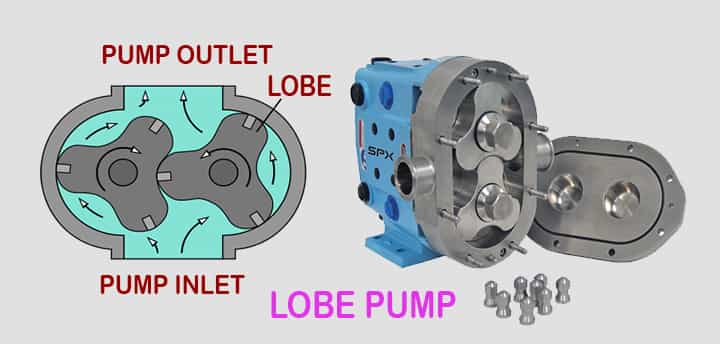
How Does Lobe Pump Work?
As both lobes are in mesh with another, they both rotate when one starts rotating. As mentioned earlier, they have fewer teeth so more discharge can be delivered but it comes at a cost of less pressure.
- Any prime mover when rotates, driver lobes rotate, and then driven lobe continues to rotate, Both these lobes rotate in opposite direction.
- A partial vacuum is created at the inlet of the pump and hence oil outside in atmospheric pressure rushes in, oil is trapped between the compact space between lobe and casing.
Clearance provided is very minimum to avoid wear. When the lobe rotates it presses oil on the casing and hence pressure gets increased.
Also here space is more and hence high discharges are achieved. At the outlet due to high pressure, oil gets pushed out.
Ge-rotor pump (Generated Rotor)
Parts of Ge-rotor pump
There is one casing inside which rests two generated rotors. One of these has external teeth while the other one is having internal teeth.
- This rotor having external teeth is the one that rotates inside the rotor having internal teeth.
- The number of teeth on the inner rotor is one less than the number of teeth on the outer rotor.
- This inner rotor is a driver to which prime mover is connected.
How Does Ge-rotor Pump Work?
As both rotors are rotating, the inner having one fewer tooth so it provides it with additional space. As outside rotor will have teeth but the inner one will have a gap between two teeth when superimposed at a specific position.
- This void that is created here will be used to pressurize fluid.
- This pocket between the outer and inner coexists, and this pocket goes on increasing from one position, and then it decreases.
- When this pocket is going through an increase in size the suction process goes on while when this pocket goes on decreasing then the fluid is forced out.
As the size of the pocket increases, outside fluid rushes in to fill this gap. This phenomenon will last until the 180-degree rotation is completed.
- Pocket will keep increasing and more and more fluid will pour in. after 180 degree rotation size of this pocket will start to reduce, which will force out the fluid to move out of the pump.
- So each pocket will be at work when rotors will be rotating.
- Oil gets sucked in first half of the rotation and gets delivered outside in other half rotation.
- There are six pockets, so at a time three are performing suction while other three are performing the delivery.
Application of Ge-rotor Pump
- As oil pump
- To pump highly viscous liquid.
Gears in Gear Pump
Mainly three types of gear are used in gear pumps. Simple spur gear, helical gear, and herringbone gear.
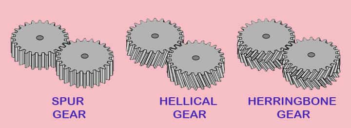
Helical gear
A helix is a type of curve produced when a straight line moves up or down on a surface of a rotating cylinder.
It has some advantages over spur gear. In spur gear entire length is in contact with the other gear.
While in the case of helical gear, this point of engagement moves along the length of the gear tooth as the gear keeps on rotating. So helical gear then operates with steady discharge pressure and fewer pulsations.
Herringbone gear
It is made of two helices spiraling in different directions from the center of the gear.
This gear also has some advantages over spur gear. As there is a pointed center section to this gear. So during a delivery stage in the case of spur gear, fluid is delivered intermittently.
- As the fluid in one gap of teeth gets delivered, after some passage of time preceding gap moves forward and fluid gets delivered.
- While in the herringbone gear, this center-pointed section also has some fluid trapped in here.
- So when earlier gap delivers than just after that fluid trapped in this center section gets delivered.
- This results in giving a smooth supply. Also, here power transmission from driving to driven is smoother.
What is Cavitation in Gear Pumps?
When fluid is used, it may be oil or water it has some air in it. So when this air gets trapped in a pocket in form of an air bubble, it sometimes implodes and that damages inter plating and moving parts.
The main reason behind it is leakage in,
- the suction port,
- unsuitable pipe sizes, and
- other elbow fittings.
Guidelines for Using a Gear Pump
- The temperature of fluid getting pumped should be in operating range.
- The whole fitting should be airtight to prolong the life of the pump and avoid cavitation.
- Gear pumps are self-lubricating pumps but still scheduled maintenance must be done.
- Gear ply has to be checked and prime mover coupling should be properly maintained.
Applications of Gear Pumps
The application of gear pumps shall be as follows,
Applications of Gear Pumps
- Different kinds of fuel oils like diesel oil, petrol, crude oil
- Different kinds of lube oils
- Petrochemicals industries
- Different kinds of chemicals
- Resins
- Paints
- Polymers
- Adhesives
- Paper industries
- Various acids and various caustics
- Asphalt
- Tar
- Food industries like sugar, butter, vegetable oils, chocolates, syrup, etc.
- Soap
- Glycol, etc.
High Rated Course
Centrifugal compressors: Principles, Operation and design
Reciprocating Compressors: Principles, Operation & Design
Understand & Predict Your Centrifugal Compressor Performance
Conclusion
Hence, we have got a basic idea about gear pumps, its parts, types, working principles, etc.
Any doubt, please let us know!
Our Apps & Quiz
Check out our ‘MechStudies – The Learning App’ in iOS
Our YouTube
Check our Animated Videos
Further Study
Refer to our most viewed articles,
great issues altogether, you just won a new reader. What would you suggest in regards to your publish that you simply made a few days in the past? Any sure?|
Hi there, just changed into alert to your blog via Google, and found that it’s really informative. I’m gonna watch out for brussels. I’ll be grateful should you proceed this in future. Many other folks will be benefited out of your writing. Cheers!|
Oh my goodness! Impressive article dude! Thank you so much, However I am having problems with your RSS. I don’t know the reason why I cannot subscribe to it. Is there anybody else having similar RSS issues? Anyone that knows the answer can you kindly respond? Thanks!!|
Greetings! Very helpful advice in this particular post! It’s the little changes which will make the greatest changes. Thanks a lot for sharing!|
Hi to all, how is the whole thing, I think every one is getting more from this web site, and your views are good for new visitors.|
I am regular reader, how are you everybody? This paragraph posted at this website is in fact pleasant.|
Hi all, here every one is sharing these familiarity, therefore it’s good to read this webpage, and I used to visit this web site daily.|